This chapter was written by Christian Psenica and reviewed by Ping He.
Learning Objectives:
This chapter provides the case structure for conjugate heat transfer (CHT) shape optimization in DAFoam. After reading this chapter, you should be able to:
- Describe how to implement two separate domains (fluid and solid) into a DAFoam CHT case
- Describe how the two domains transfer thermal data between eachother
Overview of the U-bend pipe CHT optimization case
This optimization is of a U-bend heat exchanger pipe, shown in Fig. 1. There is a solid domain (the pipe itself) as well as the inner fluid domian (air flowing within the pipe) and external fluid domain (air flowing over the outer surface of the pipe).
Case: U-bend conjugate heat transfer
Geometry: U-bend pipe with circular cross section
Objective function: Pressure loss (minimize) and heat flux (maximize)
Design variables: 36 free-form deformation (FFD) points moving in the x, y, and z directions
Mach number: 0.015 (5 m/s)
Reynolds number: 28,000
Mesh cells: ~788,000
Solver: DASimpleFoam
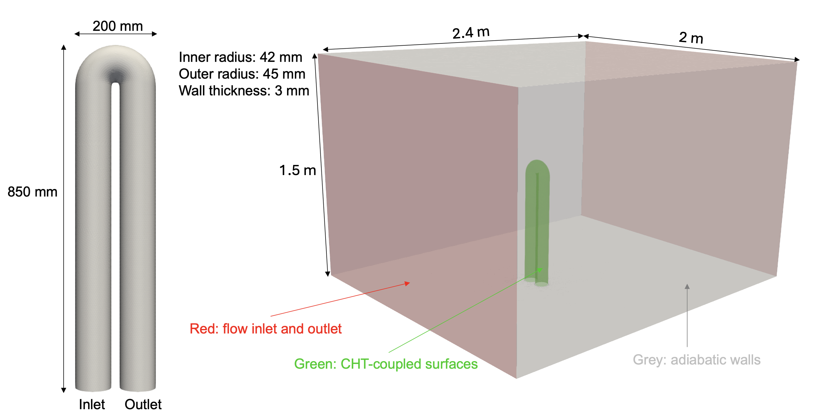
Fig. 1. Schematic of the U-bend heat exchanger configuration
Below is the file and directory structure for the U-bend CHT case in the DAFoam tutorials.
To run the optimization, first run preProcessing.sh to generate the mesh. Then run runScript.py for the optimization. If you wish to re-run the optimizaion, make sure to run Allclean.sh first.
The fluid (aero) domain is very similar to other cases we have shown in previous chapters. In light of this, we will focus on the new parts of this setup, namely, the solid (thermal) domain as well as how to handle multiple domains within runScript.py.
UBend_CHT
|-- aero              # fluid domain configuration files
  |-- 0.orig          # solid domain boundary and initial conditions
  |-- FFD             # free form deformation points
  |-- constant        # flow and turbulence property definition
  |-- system          # flow discretization and setup
  |-- paraview.foam   # dummy file for post processing the fluid domain
|-- thermal           # solid domain configuration files
  |-- 0.orig          # solid domain boundary and initial conditions
  |-- constant        # solid properties (define thermal conductivity)
  |-- system          # thermal discretization and setup
  |-- paraview.foam   # dummy file for post processing the thermal domain
|-- Allclean.sh       # script to clean up the simulation and optimization results
|-- preProcessing.sh  # generate mesh, copy the initial and boundary conditions to 0
|-- runScript.py      # main run script for DAFoam
Solid Domain
0.orig
Similar to previous cases, the 0.orig directory contains the initial and boundary conditions for our field values. It should be noted, however, that the solid domain is a conduction heat transfer problem. Therefore, there is only one field value, the temperature (distribution) of the pipe itself.
The U-bend pipe has four surfaces which need to be specified: the inner surface of the pipe (ubend_inner_solid), the outer surface of the pipe (ubend_outer_solid), and the wall surface of the pipe at the inlet and outlet (inlet_solid and outlet_solid). For this optimization case, we have two sets of CHT interfaces (inner and outer surfaces of the pipe) which take on the mixed (also known as robin type) boundary condition. We use this type of boundary condition as we must balance between temperature and heat flux at the CHT interface. The two wall surfaces at the inlet and outlet are left as zero gradient since this pipe is representative of a system of pipes. This means the pipe is connected to a pump system which pumps fluid through mutliple U-bends, not just one.
dimensions      [0 0 0 1 0 0 0];
internalField   uniform 300;

boundaryField
{
    "(ubend_inner_solid|ubend_outer_solid)"
    {
        type            mixed;
        refValue        uniform 300;
        refGradient     uniform 0;
        valueFraction   uniform 1;
    }

    "(inlet_solid|outlet_solid)"
    {
        type            zeroGradient;
    }
}
constant
As is the case with the system directory, the constant directory only needs to specify information about the pipe material itself. Hence, the only file needed in this directory is solidProperties where we specify the thermal conductivity, $k$, of the material. We simulate an aluminum pipe which has a thermal conductivity of $k=\sim200$ $\frac{W}{m*K}$. Hence in solidProperties we only see:
k 200;