What the Airfoil Agent Does
The airfoil agent supports these skills:
generate-cfd-mesh: build CFD mesh and mesh-quality outputs.run-cfd-simulation: run steady CFD from an existing mesh.run-cfd-simulation-unsteady: run unsteady CFD from an existing mesh.run-aero-optimization: run single-point aerodynamic optimization.run-multipoint-optimization: run multipoint aerodynamic optimization.run-surrogate-optimization: run surrogate-based aerodynamic shape optimization.
Standard Inputs
airfoil_profile(str, default: “naca0012”): airfoil name (for example “naca0012”, “rae2822”).mesh_cells(int, default: 6000): target total mesh-cell count for the airfoil mesh workflow.y_plus(float, default: 50.0): target near-wall spacing in wall units (y+) used to estimate the first-layer cell size d0 when it is not provided.mach_number(float, default: 0.2): freestream Mach number used together with y_plus and reynolds_number to estimate the near-wall first-layer cell size d0 when it is not provided.reynolds_number(float, default: 5e6): freestream Reynolds number used together with y_plus and mach_number to estimate the near-wall first-layer cell size d0 when it is not provided.local_refine_box(list[list[float]], default: None): optional two-corner local refinement box[[x0, y0, z0], [x1, y1, z1]]; leave unset for no local refinement.
angle_of_attack(float, default: 2.0): freestream angle of attack in degrees.fixed_lift_coeff(float, default: -1.0): automatically vary the angle of attack to compute drag at the prescribed lift coefficient. Set it to -1.0 to disable.airfoil_profile(str, default: inherited from mesh step): airfoil profile name inherited from generate-cfd-mesh and used to fit CST coefficients when needed.mach_number(float, default: inherited from mesh step): freestream Mach number.reynolds_number(float, default: inherited from mesh step): freestream Reynolds number.y_plus(float, default: inherited from mesh step): target near-wall y+ inherited from generate-cfd-mesh and used to auto-select wall functions.cst_coeffs(list[float], default: None): initial CST coefficients for the VSP geometry path ordered as[upper..., lower...]; if omitted, prepare fitsn_cst_coeffsupper andn_cst_coeffslower coefficients from the selected airfoil profile.n_cpu_cores(int, default: 1): number of MPI ranks to use for the CFD run.
angle_of_attack(float, default: 2.0): freestream angle of attack in degrees.airfoil_profile(str, default: inherited from mesh step): airfoil profile name inherited from generate-cfd-mesh and used to fit CST coefficients when needed.mach_number(float, default: inherited from mesh step): freestream Mach number.end_time(float, default: 0.1): physical end time in seconds written to controlDict endTime.delta_t(float, default: 1e-5): initial physical time-step size in seconds written to controlDict deltaT; used as a fixed step whenadjust_time_stepis false, or as the starting guess when true.max_courant_number(float, default: 2.0): maximum Courant number allowed whenadjust_time_stepis true; maps to controlDict maxCo.n_cst_coeffs(int, default: 6): number of CST coefficients per surface used when prepare fits CST coefficients.reynolds_number(float, default: inherited from mesh step): freestream Reynolds number.y_plus(float, default: inherited from mesh step): target near-wall y+ inherited from generate-cfd-mesh and used to auto-select wall functions.cst_coeffs(list[float], default: None): initial CST coefficients for the VSP geometry path ordered as[upper..., lower...]; if omitted, prepare fitsn_cst_coeffsupper andn_cst_coeffslower coefficients from the selected airfoil profile.n_cpu_cores(int, default: 1): number of MPI ranks to use for the CFD run.
angle_of_attack(float, default: 2.0): initial freestream angle of attack in degrees.airfoil_profile(str, default: inherited from mesh step): airfoil profile name inherited from generate-cfd-mesh and used to fit CST coefficients when needed.mach_number(float, default: inherited from mesh step): freestream Mach number.reynolds_number(float, default: inherited from mesh step): freestream Reynolds number.y_plus(float, default: inherited from mesh step): target near-wall y+ inherited from generate-cfd-mesh and used to auto-select wall functions.optimizer(str, default: “SLSQP”): optimization algorithm; supported values are SLSQP, IPOPT, and SNOPT.lift_constraint(float, default: 0.5): target lower-bound lift coefficient constraint.max_opt_iters(int, default: 50): maximum number of optimization iterations.thickness_constraint(float, default: 0.5): lower bound on normalized airfoil thickness; 1.0 means the optimized airfoil thickness is the same as the baseline, and a negative value disables it.le_radius_constraint(float, default: 0.7): lower bound on normalized leading-edge radius; 1.0 means the optimized leading-edge radius is the same as the baseline, and a negative value disables it.volume_constraint(float, default: 1.0): lower bound on normalized airfoil volume; 1.0 means the optimized airfoil volume is the same as the baseline, and a negative value disables it.cst_coeffs(list[float], default: None): initial CST coefficients for the VSP geometry path ordered as[upper..., lower...]; if omitted, prepare fitsn_cst_coeffsupper andn_cst_coeffslower coefficients from the selected airfoil profile.n_cpu_cores(int, default: 1): number of MPI ranks to use for the optimization run.
weights(list[float], default: [0.5, 0.5]): weight for each flight condition in the multipoint objective function; must have one entry per scenario and sum to 1.0.angle_of_attack(list[float], default: [5.0, 4.0]): initial angle of attack in degrees for each flight condition.lift_constraint(list[float], default: [0.5, 0.4]): target lift coefficient for each flight condition.airfoil_profile(str, default: inherited from mesh step): airfoil profile name inherited from generate-cfd-mesh and used to fit CST coefficients when needed.mach_number(float, default: inherited from mesh step): freestream Mach number.y_plus(float, default: inherited from mesh step): target near-wall y+ inherited from generate-cfd-mesh and used to auto-select wall functions.n_cst_coeffs(int, default: 6): number of CST coefficients per surface used when prepare fits CST coefficients.reynolds_number(float, default: inherited from mesh step): freestream Reynolds number.optimizer(str, default: “SLSQP”): optimization algorithm; supported values are SLSQP, IPOPT, and SNOPT.max_opt_iters(int, default: 100): maximum number of optimization iterations.thickness_constraint(float, default: 0.5): lower bound on normalized airfoil thickness; 1.0 means the optimized airfoil thickness is the same as the baseline, and a negative value disables it.le_radius_constraint(float, default: -1.0): lower bound on normalized leading-edge radius; 1.0 means the optimized leading-edge radius is the same as the baseline, and a negative value disables it.cst_coeffs(list[float], default: None): initial CST coefficients ordered as[upper..., lower...]; if omitted, prepare fitsn_cst_coeffsupper and lower coefficients from the selected airfoil profile.n_cpu_cores(int, default: 1): number of MPI ranks to use for the optimization run.
criterion(str, default: “EI”): criterion for next evaluation point determination.iters(int, default: 5): number of iterations to optimize the objective function.numDOE(int, default: 24): number of DOE points used in the surrogate model.seed(int, default: 45): seed value to replicate results.objPenalty(float, default: 100): penalty factor on the objective function for failed CFD runs.cst_bounds(float, default: [0.3, 0.3, 0.3, 0.3, 0.3, 0.3]): array of CST design-variable bound scaling factors; bounds are computed as baselineValue * (1 +/- cst_bound).conWeight(float, default: 1e5): scalar constraint-violation weight; when multiple weights are provided, they must follow the constraint order.maxIter(int, default: 50): maximum number of surrogate-model optimization iterations.nStart(int, default: 50): number of optimization start points.qEI(str, default: “KBLB”): method for maximizing q-EI.surrogate(str, default: “KRG”): surrogate model type.mach_number(float, default: inherited from mesh step): freestream Mach number.reynolds_number(float, default: inherited from mesh step): freestream Reynolds number.y_plus(float, default: inherited from mesh step): target near-wall y+ inherited from generate-cfd-mesh and used to auto-select wall functions.n_cst_coeffs(int, default: 6): number of CST coefficients per surface used when prepare fits CST coefficients.cst_coeffs(list[float], default: None): initial CST coefficients for the VSP geometry path ordered as[upper..., lower...]; if omitted, prepare fitsn_cst_coeffsupper andn_cst_coeffslower coefficients from the selected airfoil profile.angle_of_attack(float, default: 2.0): initial freestream angle of attack in degrees.lift_constraint(float, default: 0.5): target lower-bound lift coefficient constraint.thickness_constraint(float, default: 0.5): lower bound on normalized airfoil thickness; 1.0 means the optimized airfoil thickness is the same as the baseline, and a negative value disables it.le_radius_constraint(float, default: 0.7): lower bound on normalized leading-edge radius; 1.0 means the optimized leading-edge radius is the same as the baseline, and a negative value disables it.volume_constraint(float, default: 1.0): lower bound on normalized airfoil volume; 1.0 means the optimized airfoil volume is the same as the baseline, and a negative value disables it.airfoil_profile(str, default: inherited from mesh step): airfoil profile name inherited from generate-cfd-mesh and used to fit CST coefficients when needed.
Advanced Parameters
blunt_te(float, default: 0.01): trailing-edge round percentage expressed as an x/chord trim location; 0.01 means the trim starts at x = 0.01 from the trailing edge.d0(float, default: -1.0): first-layer height in meters; use a negative value to let the wrapper estimate it fromy_plus,mach_number, andreynolds_number.hyperbolic_sweeps(int, default: 20): number of smoothing sweeps per layer for hyperbolic extrusion.neighbor_rings(int, default: 5): neighbor-ring depth used by the hyperbolic extrusion smoother.diffuse_start(float, default: 0.002): smoothing onset distance in meters; hyperbolic diffusion stays off until this marched distance, then starts ramping up.max_nonorthogonality_pass(float, default: 70.0): pass threshold for maximum non-orthogonality.max_nonorthogonality_warning(float, default: 80.0): warning threshold for maximum non-orthogonality.max_aspect_ratio_pass(float, default: 1000.0): pass threshold for maximum aspect ratio.max_aspect_ratio_warning(float, default: 5000.0): warning threshold for maximum aspect ratio.max_skewness_pass(float, default: 4.0): pass threshold for maximum skewness.max_skewness_warning(float, default: 6.0): warning threshold for maximum skewness.
transonic_mach_boundary(float, default: 0.4): transonic Mach split used by the default solver selection whensolver_nameis not set.solver_name(str, default: null): explicit solver override; supported values areDASimpleFoam,DARhoSimpleFoam,DARhoSimpleCFoam, andDAHisaFoam; leave unset,null, ornoneto use the default Mach-based selection.turbulence_model(str, default: “SpalartAllmaras”): OpenFOAM RANS turbulence model; supported values areSpalartAllmarasandkOmegaSST.use_wall_functions(str, default: “auto”): wall-function selection; useautoto choose from mesh settings,1to force enable, or0to force disable.max_flow_iters(int, default: 10000): maximum number of flow iterations written to the case controlDict endTime/writeInterval settings.n_cst_coeffs(int, default: 6): number of CST coefficients per surface used when prepare fits CST coefficients; for example,6means 6 upper and 6 lower coefficients.primal_func_std_tol(float, default: 0.04): DAFoam primal function standard deviation tolerance passed to script_run_dafoam.py.primal_func_slope_tol(float, default: 1e-6): DAFoam primal function slope tolerance passed to script_run_dafoam.py.force_std_pass(float, default: 0.0001): pass threshold for raw force-coefficient standard deviation.force_std_warning(float, default: 0.05): warning threshold for raw force-coefficient standard deviation.residual_drop_orders_pass(float, default: 6.0): pass threshold for minimum residual drop in log10 orders.residual_drop_orders_warning(float, default: 3.0): warning threshold for minimum residual drop in log10 orders.initialize_from(str, default: null): warm-start source case name of a previously converged CFD run; leave unset for a cold start.cp_plot_lower_bound(float, default: -2.0): lower bound of the Cp axis and colorbar shared by the pressure-profile and Cp flow-field plots.cp_plot_upper_bound(float, default: 2.0): upper bound of the Cp axis and colorbar shared by the pressure-profile and Cp flow-field plots.u_plot_lower_bound(float, default: -1.0): lower bound of the normalized velocity colorbar for the U flow-field plot.u_plot_upper_bound(float, default: 1.0): upper bound of the normalized velocity colorbar.
transonic_mach_boundary(float, default: 0.4): transonic Mach split used by the default solver selection whensolver_nameis not set.solver_name(str, default: null): explicit solver override; supported values areDASimpleFoam,DARhoSimpleFoam,DARhoSimpleCFoam, andDAHisaFoam; leave unset,null, ornoneto use the default Mach-based selection.turbulence_model(str, default: “SpalartAllmaras”): OpenFOAM RANS turbulence model; supported values areSpalartAllmarasandkOmegaSST.use_wall_functions(str, default: “auto”): wall-function selection; useautoto choose from mesh settings,1to force enable, or0to force disable.force_std_pass(float, default: 0.0001): pass threshold for raw force-coefficient standard deviation.force_std_warning(float, default: 0.05): warning threshold for raw force-coefficient standard deviation.cp_plot_lower_bound(float, default: -2.0): lower bound of the Cp axis and colorbar shared by the pressure-profile and Cp flow-field plots.cp_plot_upper_bound(float, default: 2.0): upper bound of the Cp axis and colorbar shared by the pressure-profile and Cp flow-field plots.u_plot_lower_bound(float, default: -1.0): lower bound of the normalized velocity colorbar for the U flow-field plot.u_plot_upper_bound(float, default: 1.0): upper bound of the normalized velocity colorbar.
transonic_mach_boundary(float, default: 0.4): transonic Mach split used by the default solver selection whensolver_nameis not set.solver_name(str, default: null): explicit solver override; supported values areDASimpleFoam,DARhoSimpleFoam,DARhoSimpleCFoam, andDAHisaFoam; leave unset,null, ornoneto use the default Mach-based selection.turbulence_model(str, default: “SpalartAllmaras”): OpenFOAM RANS turbulence model; supported values areSpalartAllmarasandkOmegaSST.use_wall_functions(str, default: “auto”): wall-function selection; useautoto choose from mesh settings,1to force enable, or0to force disable.max_flow_iters(int, default: 10000): maximum number of flow iterations written to the case controlDict endTime/writeInterval settings.max_adj_iters(int, default: 1000): maximum GMRES iterations for the DAFoam adjoint linear solve.pc_fill_level(int, default: 1): ILU fill level for the DAFoam adjoint preconditioner.n_cst_coeffs(int, default: 6): number of CST coefficients per surface used when prepare fits CST coefficients; for example,6means 6 upper and 6 lower coefficients.primal_func_std_tol(float, default: 0.04): DAFoam primal function standard deviation tolerance passed to script_run_dafoam.py.primal_func_slope_tol(float, default: 1e-6): DAFoam primal function slope tolerance passed to script_run_dafoam.py.objective_reduction_pct_pass(float, default: 5.0): pass threshold for objective reduction in percent.objective_reduction_pct_warning(float, default: 1.0): warning threshold for objective reduction in percent.final_feasibility_pass(float, default: 0.0001): pass threshold for final feasibility.final_feasibility_warning(float, default: 0.01): warning threshold for final feasibility.flow_residual_drop_orders_pass(float, default: 6.0): pass threshold for minimum flow residual drop in log10 orders.flow_residual_drop_orders_warning(float, default: 3.0): warning threshold for minimum flow residual drop in log10 orders.adjoint_residual_drop_orders_pass(float, default: 5.0): pass threshold for minimum adjoint residual drop in log10 orders.adjoint_residual_drop_orders_warning(float, default: 3.0): warning threshold for minimum adjoint residual drop in log10 orders.cp_plot_lower_bound(float, default: -2.0): lower bound of the Cp axis and colorbar shared by the pressure-profile and Cp flow-field plots.cp_plot_upper_bound(float, default: 2.0): upper bound of the Cp axis and colorbar shared by the pressure-profile and Cp flow-field plots.u_plot_lower_bound(float, default: -1.0): lower bound of the normalized velocity colorbar for the U flow-field plot.u_plot_upper_bound(float, default: 1.0): upper bound of the normalized velocity colorbar.
transonic_mach_boundary(float, default: 0.4): transonic Mach split used by the default solver selection whensolver_nameis not set.solver_name(str, default: null): explicit solver override; supported values areDASimpleFoam,DARhoSimpleFoam,DARhoSimpleCFoam, andDAHisaFoam; leave unset,null, ornoneto use the default Mach-based selection.use_wall_functions(str, default: “auto”): wall-function selection; useautoto choose from mesh settings,1to force enable, or0to force disable.max_adj_iters(int, default: 1000): maximum GMRES iterations for the DAFoam adjoint linear solve.pc_fill_level(int, default: 1): ILU fill level for the DAFoam adjoint preconditioner.cp_plot_lower_bound(float, default: -2.0): lower bound of the Cp axis and colorbar shared by the pressure-profile and Cp flow-field plots.cp_plot_upper_bound(float, default: 2.0): upper bound of the Cp axis and colorbar shared by the pressure-profile and Cp flow-field plots.u_plot_lower_bound(float, default: -1.0): lower bound of the normalized velocity colorbar for the U flow-field plot.u_plot_upper_bound(float, default: 1.0): upper bound of the normalized velocity colorbar.objective_reduction_pct_pass(float, default: 5.0): pass threshold for objective reduction in percent.objective_reduction_pct_warning(float, default: 1.0): warning threshold for objective reduction in percent.final_feasibility_pass(float, default: 0.0001): pass threshold for final feasibility.final_feasibility_warning(float, default: 0.01): warning threshold for final feasibility.flow_residual_drop_orders_pass(float, default: 6.0): pass threshold for minimum flow residual drop in log10 orders.flow_residual_drop_orders_warning(float, default: 3.0): warning threshold for minimum flow residual drop in log10 orders.adjoint_residual_drop_orders_pass(float, default: 5.0): pass threshold for minimum adjoint residual drop in log10 orders.adjoint_residual_drop_orders_warning(float, default: 3.0): warning threshold for minimum adjoint residual drop in log10 orders.
transonic_mach_boundary(float, default: 0.4): transonic Mach split used by the default solver selection whensolver_nameis not set.solver_name(str, default: null): explicit solver override; supported values areDASimpleFoam,DARhoSimpleFoam,DARhoSimpleCFoam, andDAHisaFoam; leave unset,null, ornoneto use the default Mach-based selection.use_wall_functions(str, default: “auto”): wall-function selection; useautoto choose from mesh settings,1to force enable, or0to force disable.max_flow_iters(int, default: 3000): max flow iterations.initialize_from(str, default: null): warm-start source case name; when set, the field staged into 0/ is kept instead of resetting to the uniform freestream.primal_func_std_tol(float, default: 0.04): primal function standard deviation tolerance.primal_func_slope_tol(float, default: 1e-6): primal function slope tolerance.n_cpu_cores(int, default: 2): number of MPI ranks to use for the optimization run.
Agent Capability demos
Mesh Generation
Users can prompt to generate airfoil mesh with desired airfoil profiles, mesh densities, yPlus, and local refinement.
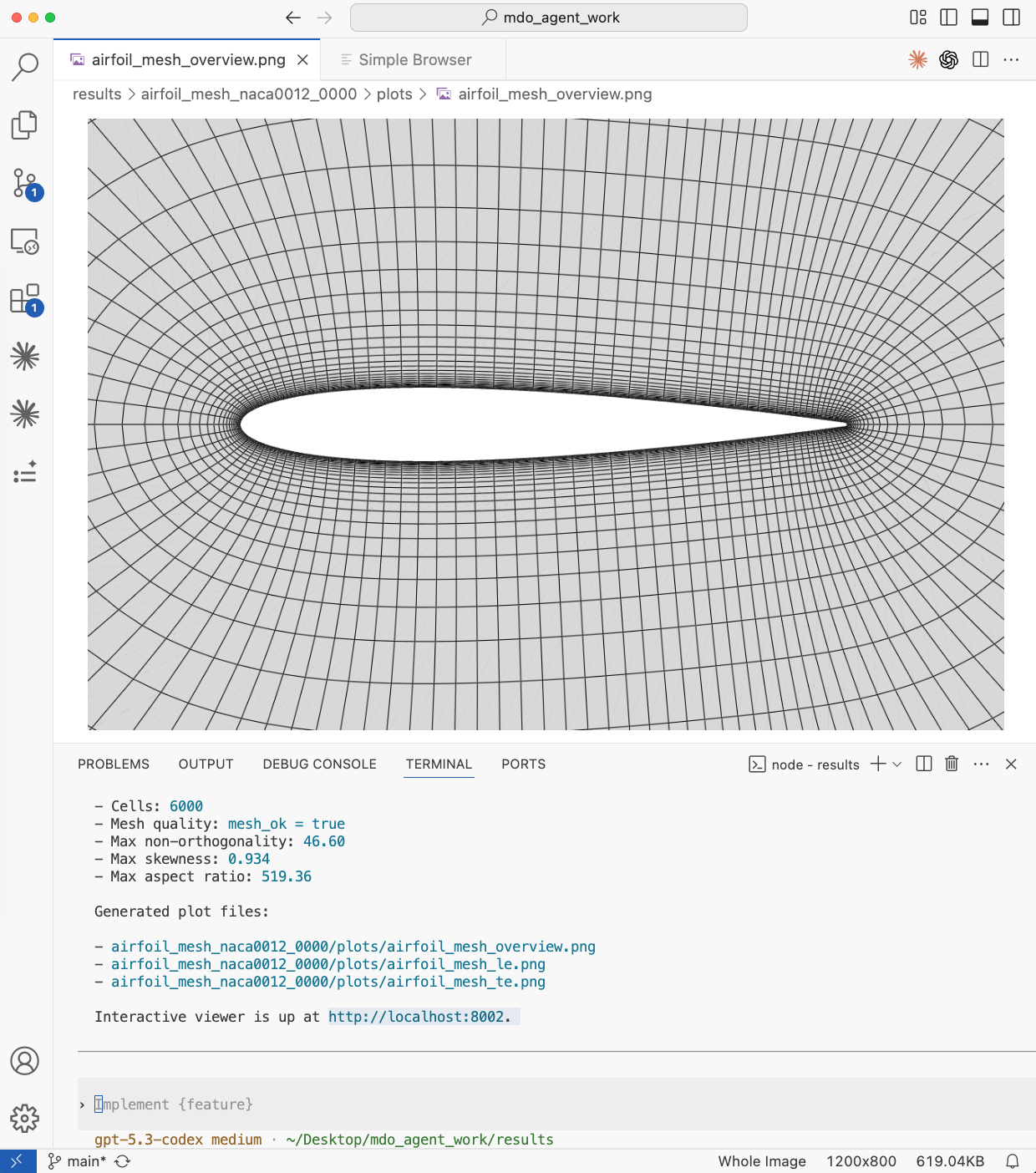
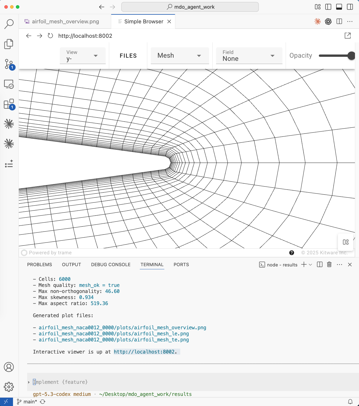
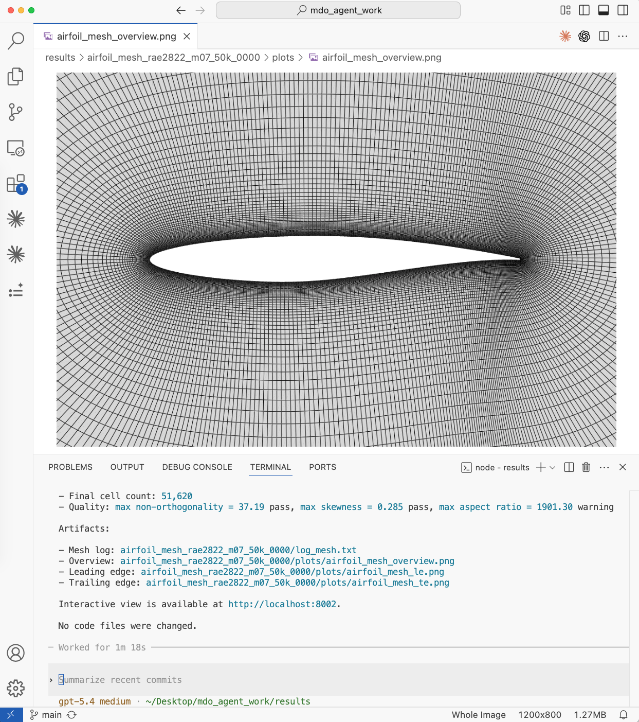
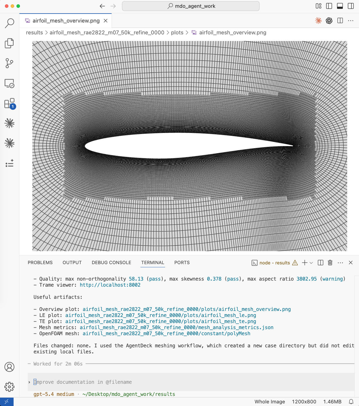
Fig. 1. Top left: Overview of a coarse mesh. Prompt: Generate a cfd mesh for the naca0012 airfoil. Top right: Trame interactive view of the TE mesh. Bottom left: Overview of a fine mesh with a different airfoil. Prompt: Generate a cfd mesh for the rae2822 airfoil with 50K cells, yPlus 3, and ref Mach=0.7. Bottom right: Locally refined mesh. Prompt: Locally refine the above mesh between -0.1 to 1.1 chords from LE, z length of the refinment is 0.5 chords.
CFD Simulation
Users can prompt to run airfoil CFD simulations with desired airfoil profiles (prescribed in the mesh generation skill), angles of attack, Mach numbers, and Reynolds numbers. For example,
Generate a cfd mesh for the naca0012 airfoil and run a cfd simulation at Ma=0.3, Re=5e6, and aoa=3 degs. Use 2 CPU cores.
Or a supersonic flow case
Generate a cfd mesh for rae2822 airfoil with 100K cells, yPlus 5, Re 2e7 and Ma 1.5. Run a cfd with aoa=1 deg use 4 cores..
The following are the agent-generated figures.
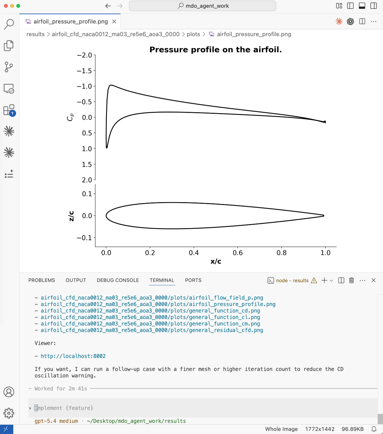
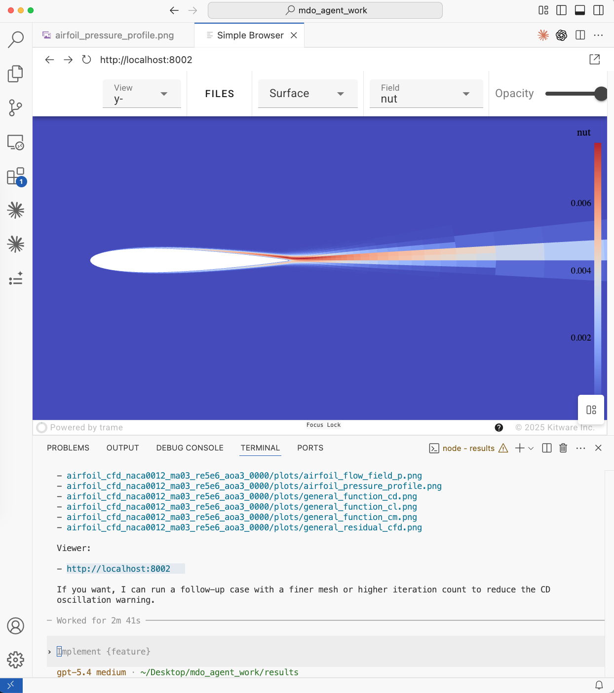
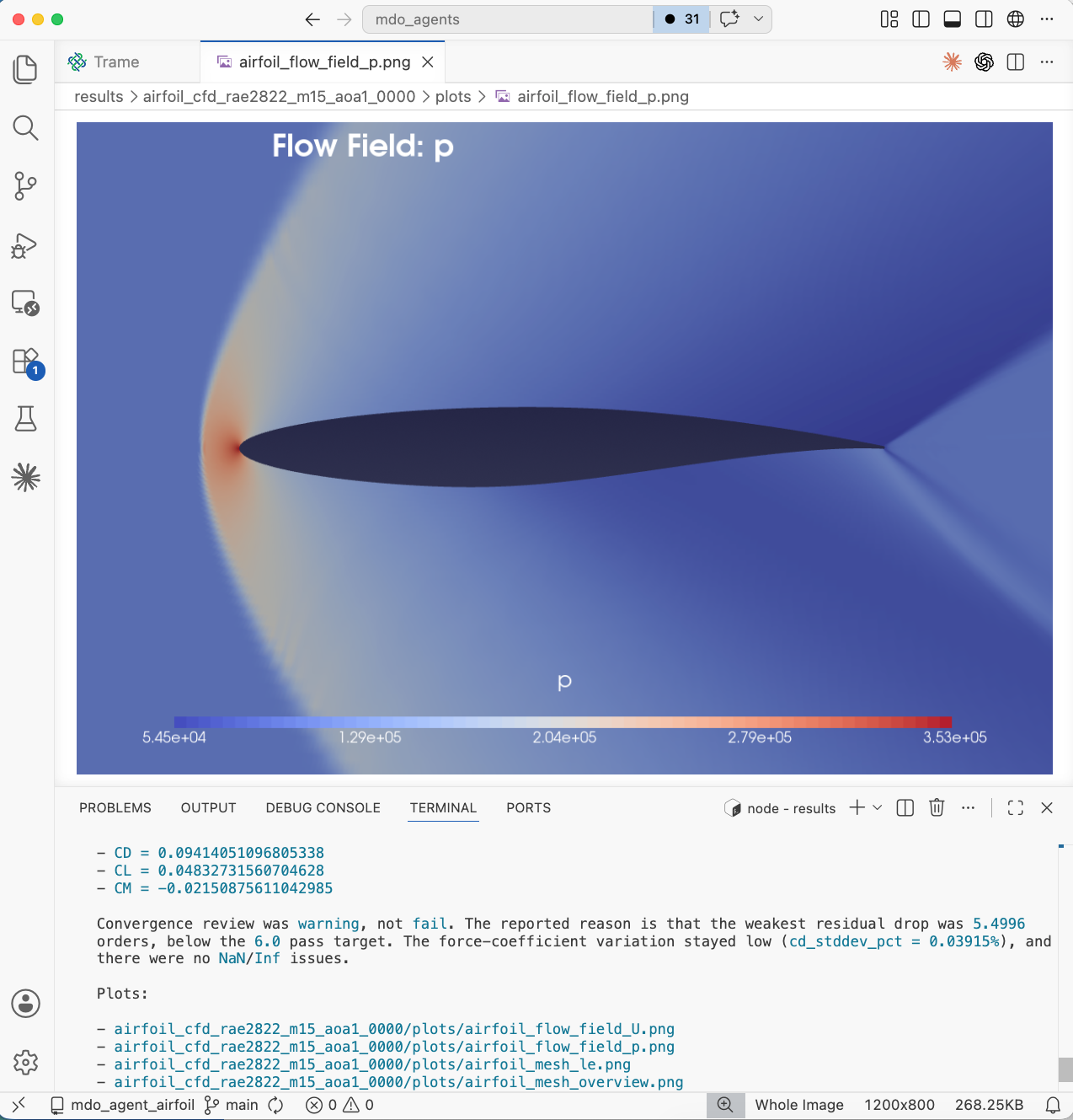
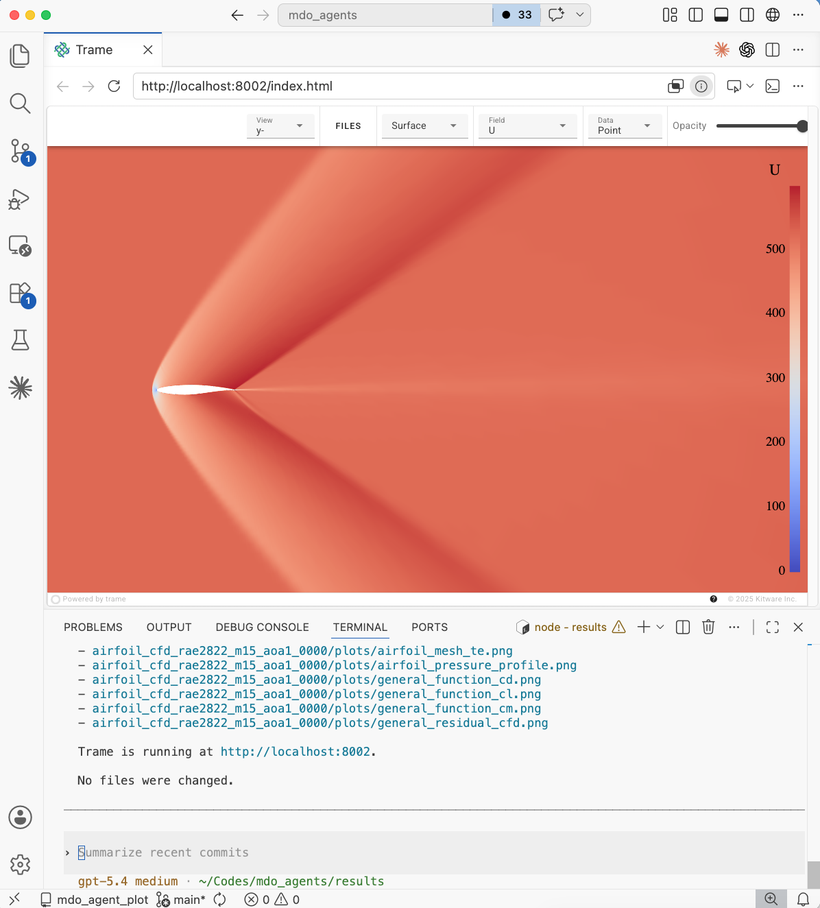
Fig. 2. Top left: Airfoil pressure profile. Top right: Visualization of airfoil turbulence variable field in the trame interactive server. Bottom left and right: pressure and velocity contours of the supersonic csaae.
CFD Unsteady Simulation
Users can prompt to run airfoil CFD simulations with desired airfoil profiles (prescribed in the mesh generation skill), angles of attack, Mach numbers, and Reynolds numbers. For example,
Generate a cfd mesh for naca0012 airfoil with 20K cells, Re 5e6 and Ma 0.3. Run a unsteady cfd simulation with aoa=20 deg use 4 cores..
The following are the agent-generated figures.
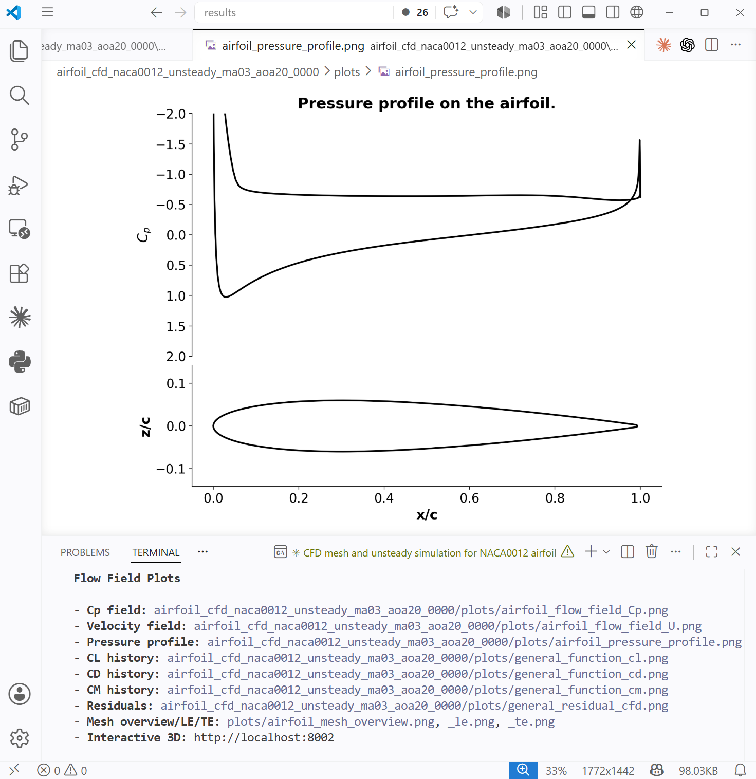
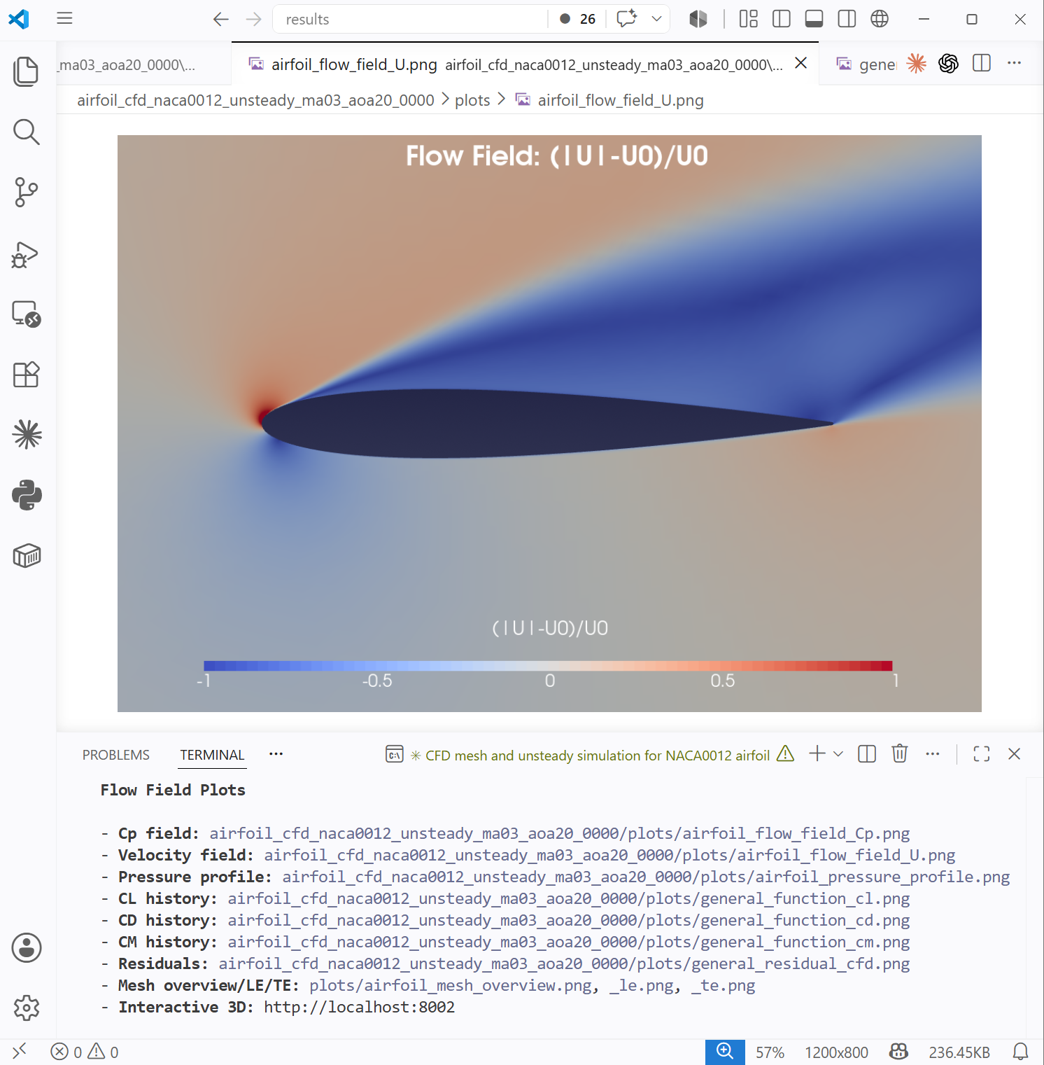
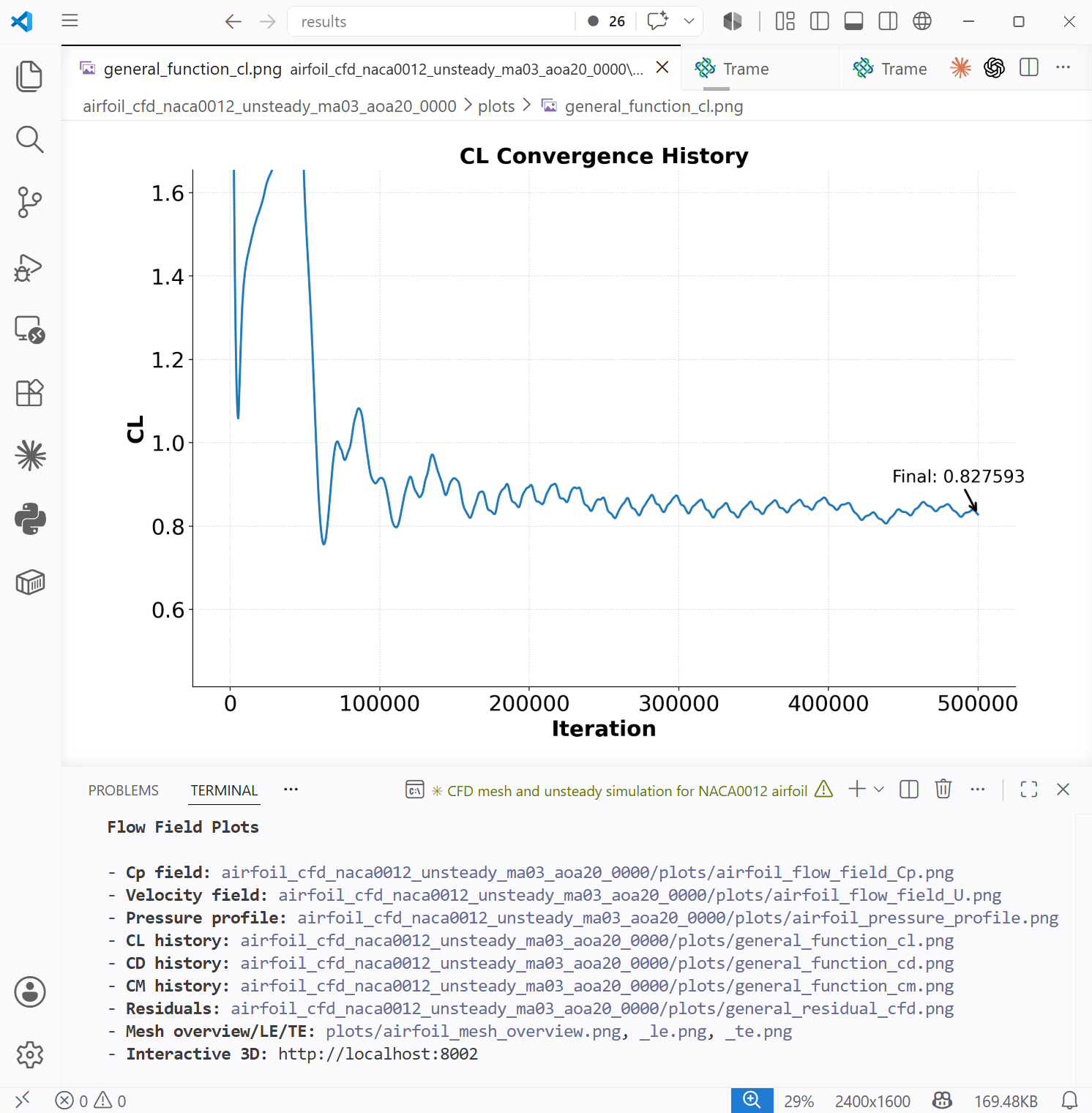
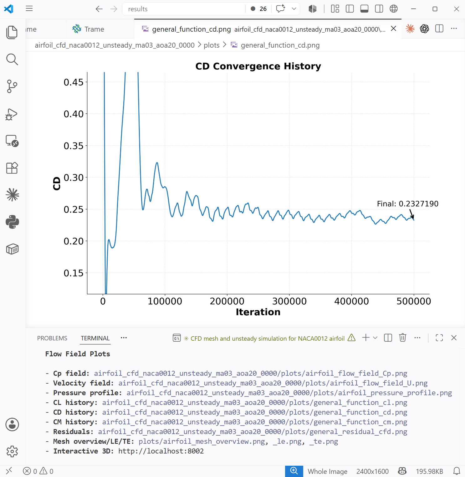
Fig. x. Top left: Airfoil pressure profile. Top right: Visualization of airfoil velocity field in the trame interactive server. Bottom left and right: lift coefficient convergence history and drag coefficient convergence history.
CFD Mesh Convergence Study
Users can prompt to conduct a mesh convergence study for an airfoil. For example,
Conduct a cfd mesh convergence study for the RAE2822 airfoil at Ma=0.75, Re=1e7, and aoa=2 degs. The mesh sizes are 10K, 20K, 50K, and 100K. The yPlus is 3. Use 24 cores. CFD maxIter=5000.
The following is the agent-generated figure, one needs to add a follow up prompt to plot this pressure profile comparisoin figure, such as
Plot the pressure profile for all cases in one figure to show the difference.
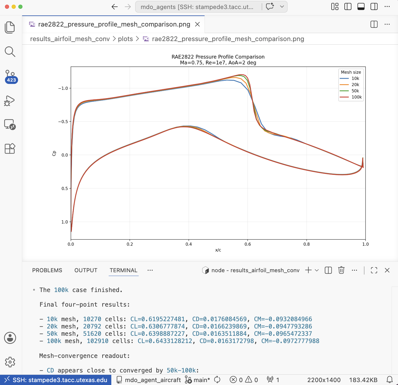
Fig. 3. Pressure profile comparison between different mesh densities.
CD/CL vs AoA
Users can prompt to simulation CD/CL sweep for various angle of attacks. For example,
Generate a cfd mesh for the naca0012 airfoil with 50K cells and yPlus 3. Then, run a sweep of CFD at Ma=0.3 and Re=5e6, and aoa = 2 to 18 degs with 2 deg interval. Use 24 cores. After the simulation is finished, plot cl/cd vs aoa and drop diverged cases..
The following is the agent-generated figure. This case ran on the HPC and you may need to follow up to ask the agent to analyze the result once the job is finished on compute nodes.
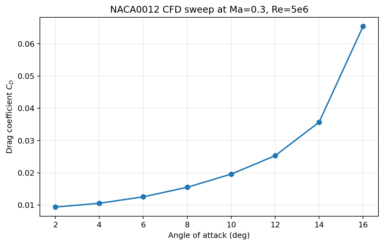
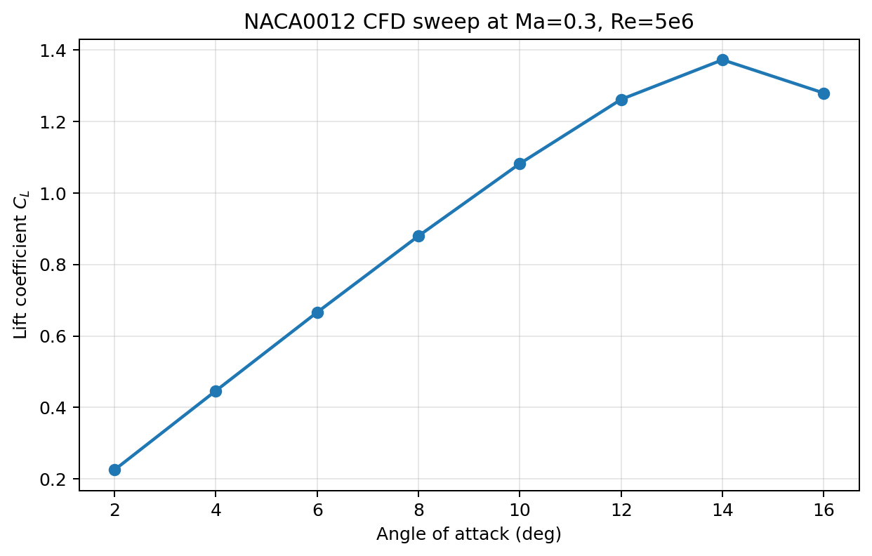
Fig. 4. CD/CL vs AoA plots
Aerodyanamic shape optimization
Users can prompt to run aerodynamic shape optimization. The default objective is drag, the design variables are airfoil shape and angle of attack, the constraints include lift, thickness, volume, and leading edge radius. For example,
Generate a cfd mesh for the naca0012 airfoil and run an aero optimization at ma 0.3, re 5e6, cl 0.5. Run the optimization for 20 iters. Use 2 cores.
The following is the agent-generated figure. The drag reduction and constraints can be found in the chat window after the optimization is finished. After the optimization is finished, the user can also ask agent to verify the drag reduction generated by the coarse-mesh optimization with a fine mesh. For example
The optimization uses a coarse mesh. Verify the optimization drag reduction at CL 0.5 using a fine mesh with 50K cells and yPlus 3. Run two fine mesh CFDs for the baseline and optimized designs and compare with the coarse mesh results.
The agent will compare the drag reduciton between coarse and fine mesh for the baseline and optimized designs.
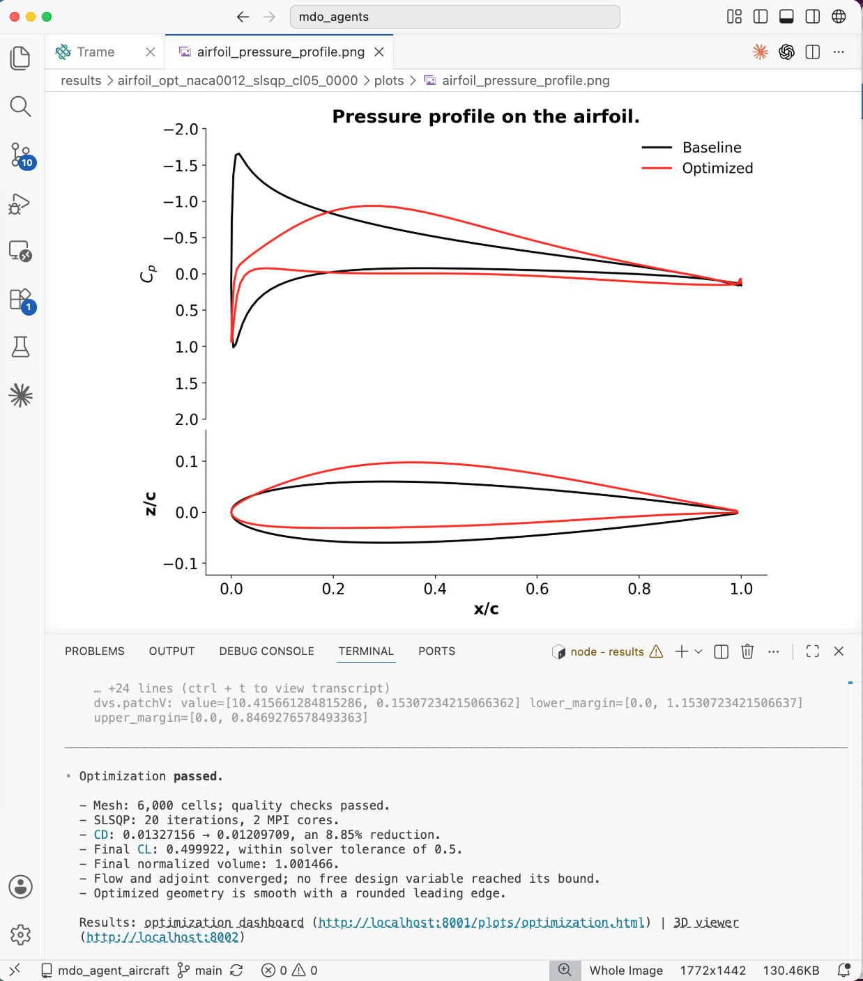
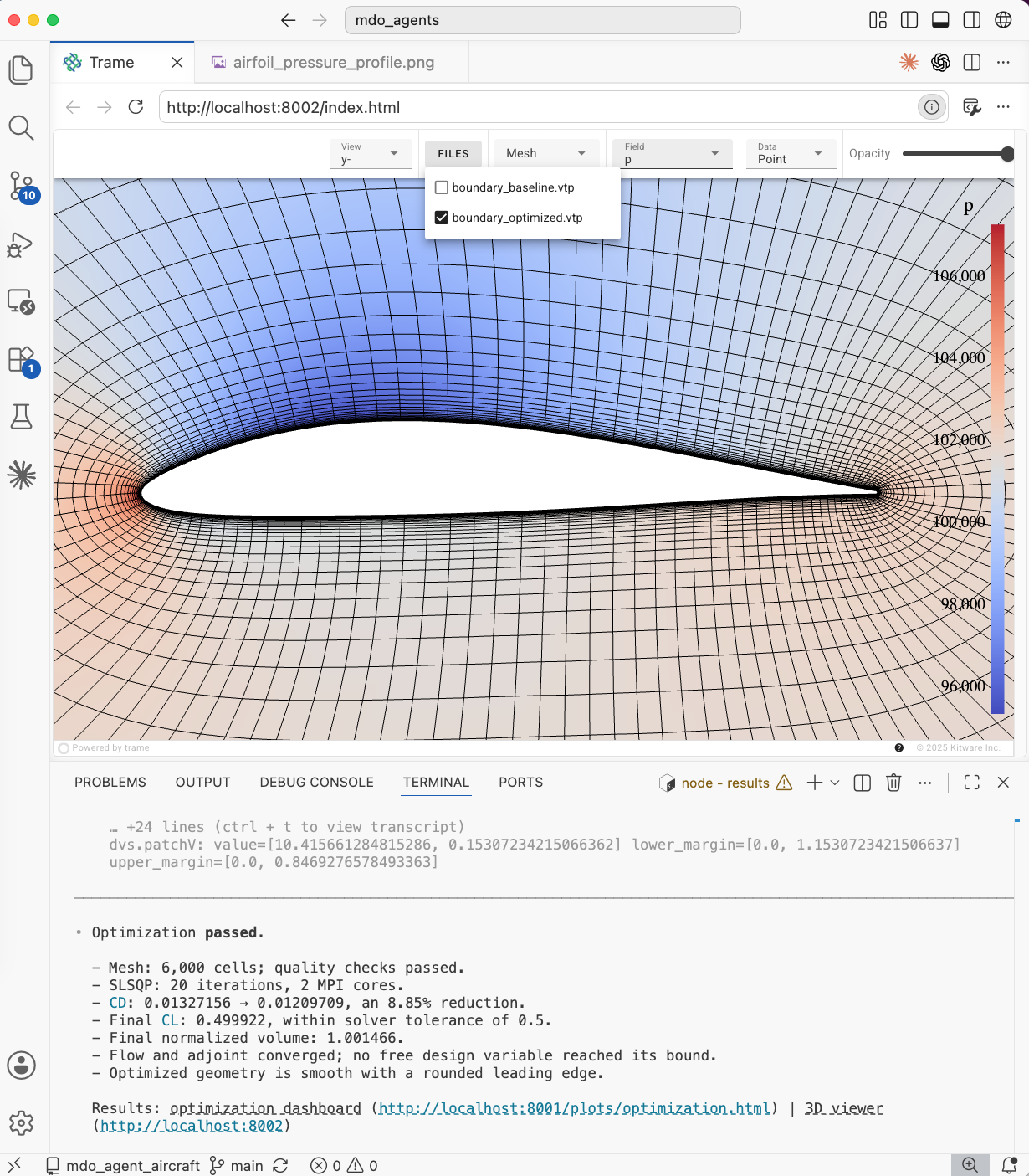
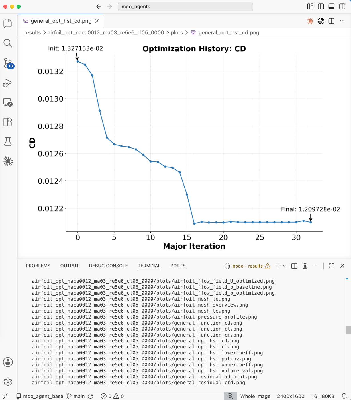
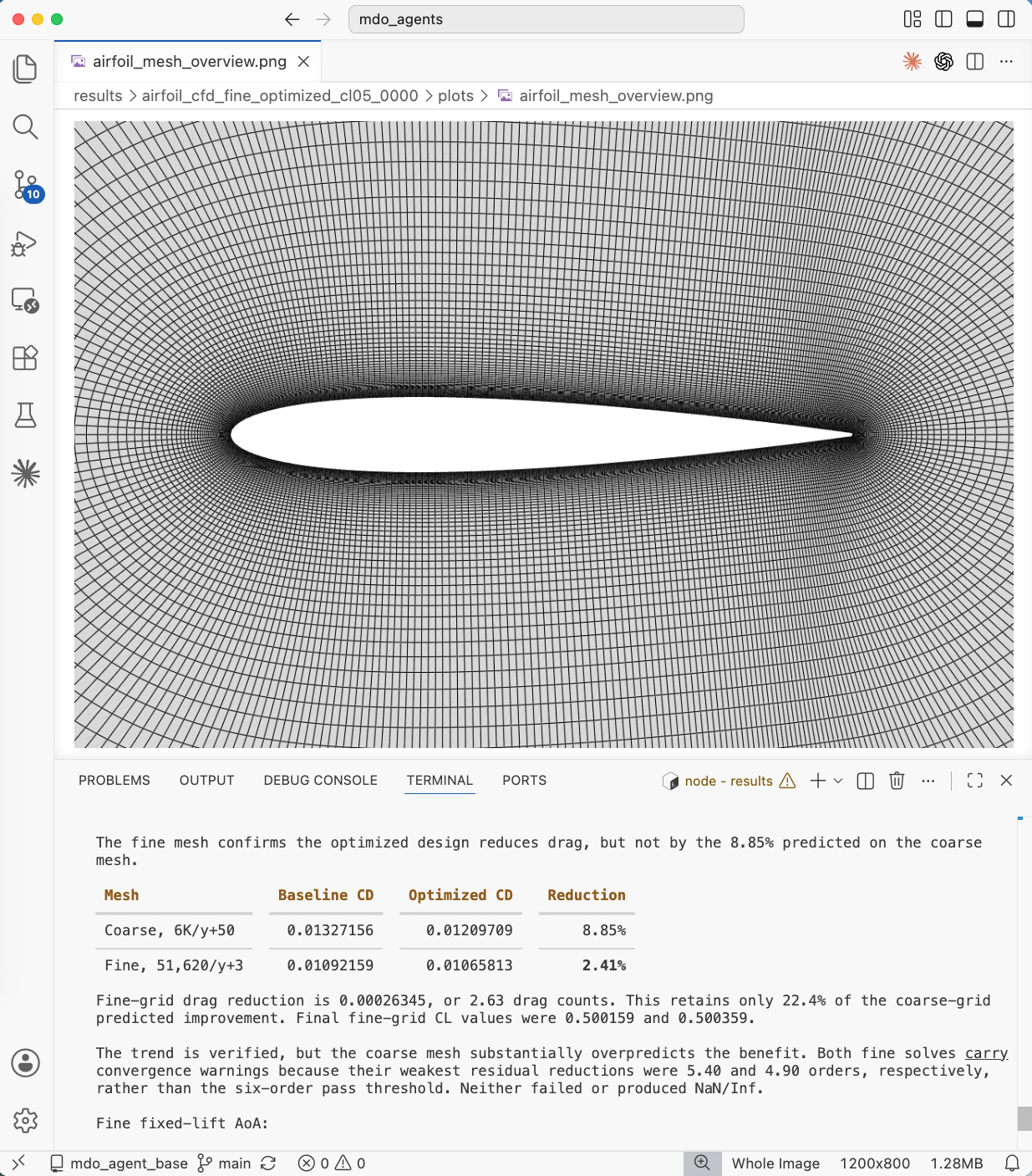
Fig. 5. Aerodynamic optimization. Top Left: comparison of the pressure and shape between the baseline and optimized designs. Top Right: Visualizing of the pressure for optimized design in trame. Bot left: Optimization convergence history for CD. Bot right: Summary of fine mesh verification.
Surrogate-based aerodyanamic shape optimization
Users can additionally choose to use a surrogate-based optimization method rather than gradient-based. Similar to the gradient-based approach, the design variables include the shape of the airfoil and the angle of attack subject to the same lift, thickness, volume, and leading edge radius constraints. For example,
Run a surrogate based optimization on the NACA0012 airfoil. Set Re to 6.6e5, use 4000 mesh cells, with a velocity of 10m/s velocity. For the lift constraint use 0.5 and set the AOA to 5. Use 80 DOE points for the optimization and set the bounds on the CST coefficient design variables to 0.5. Use 10 optimization iterations. For the lift constraint weight use 1e16 and a weight of 10 for all other constraints. Use 22 cores for the CFD. Use the KPLS surrogate model.
The following is the agent generated figure. The drag reduction and constraint values are returned to the user by the agent in the chat window.
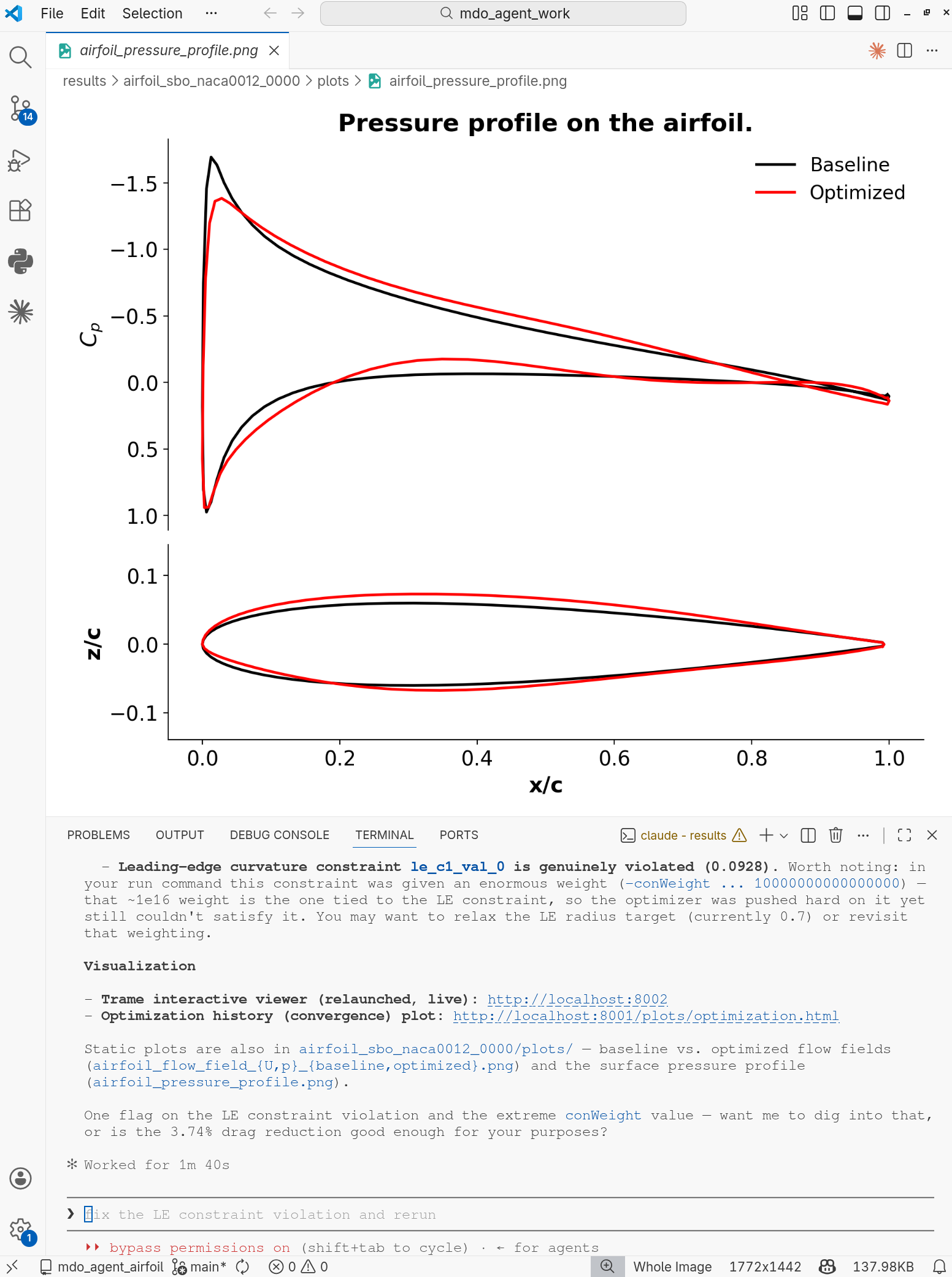
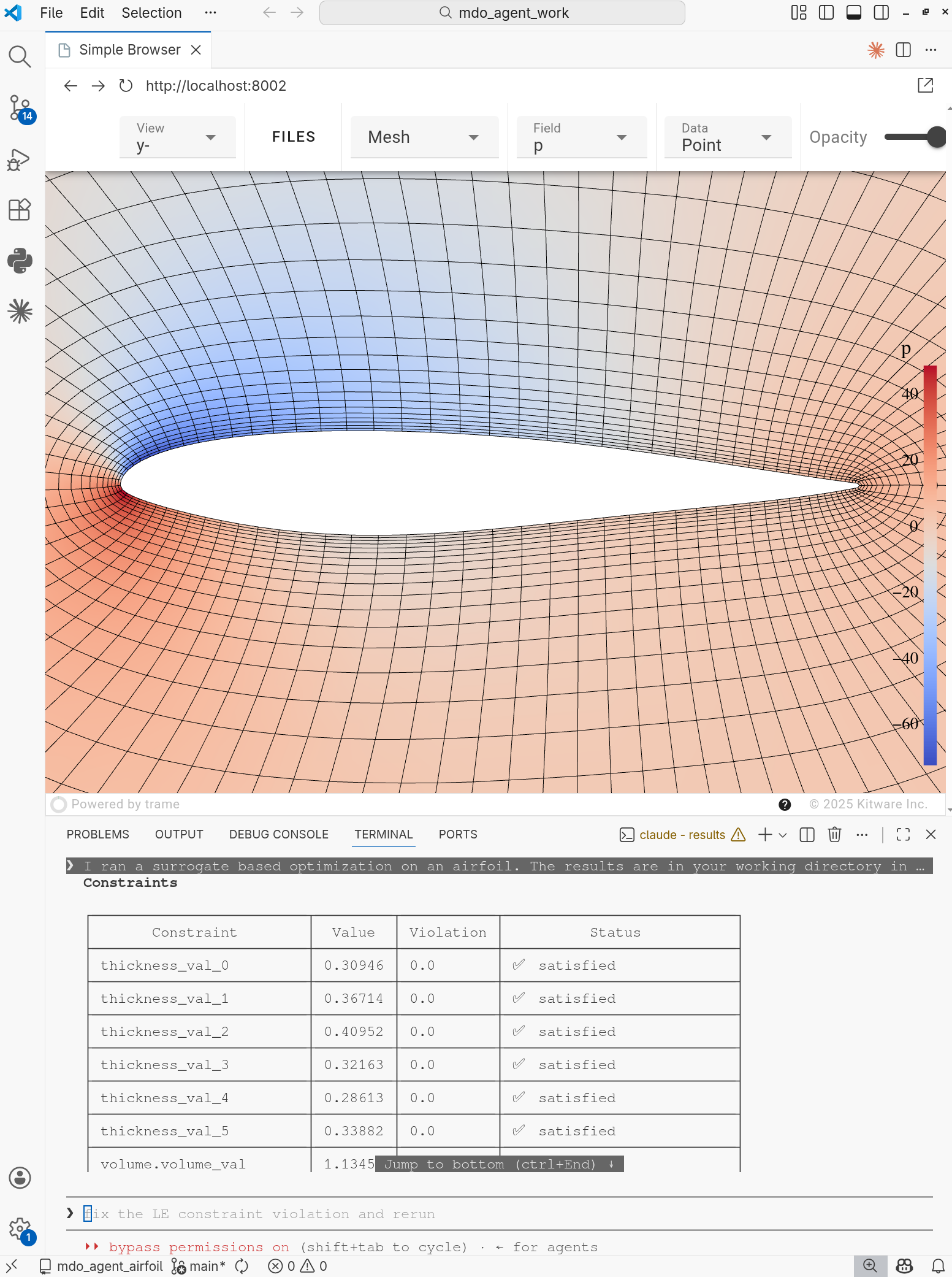
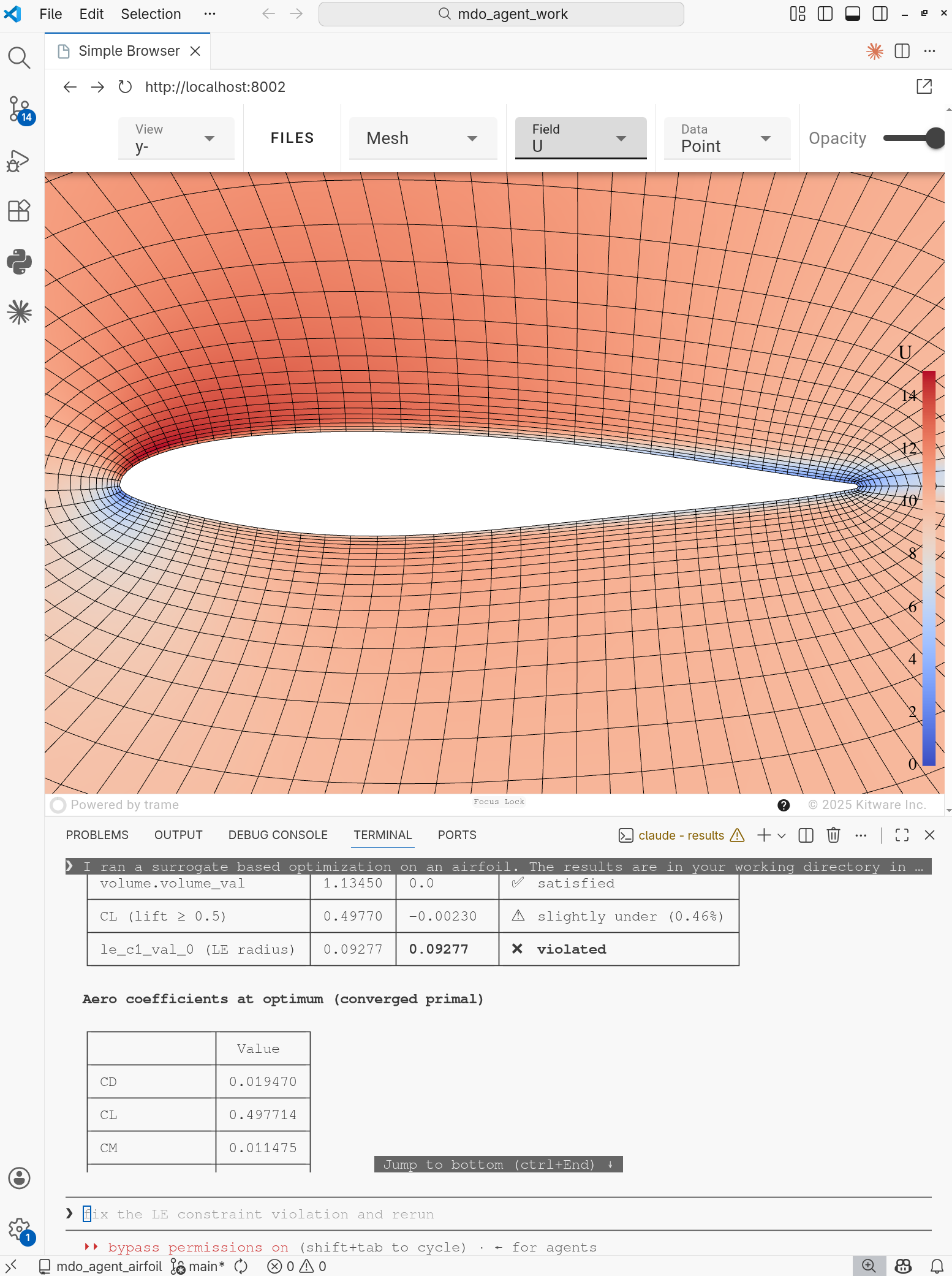
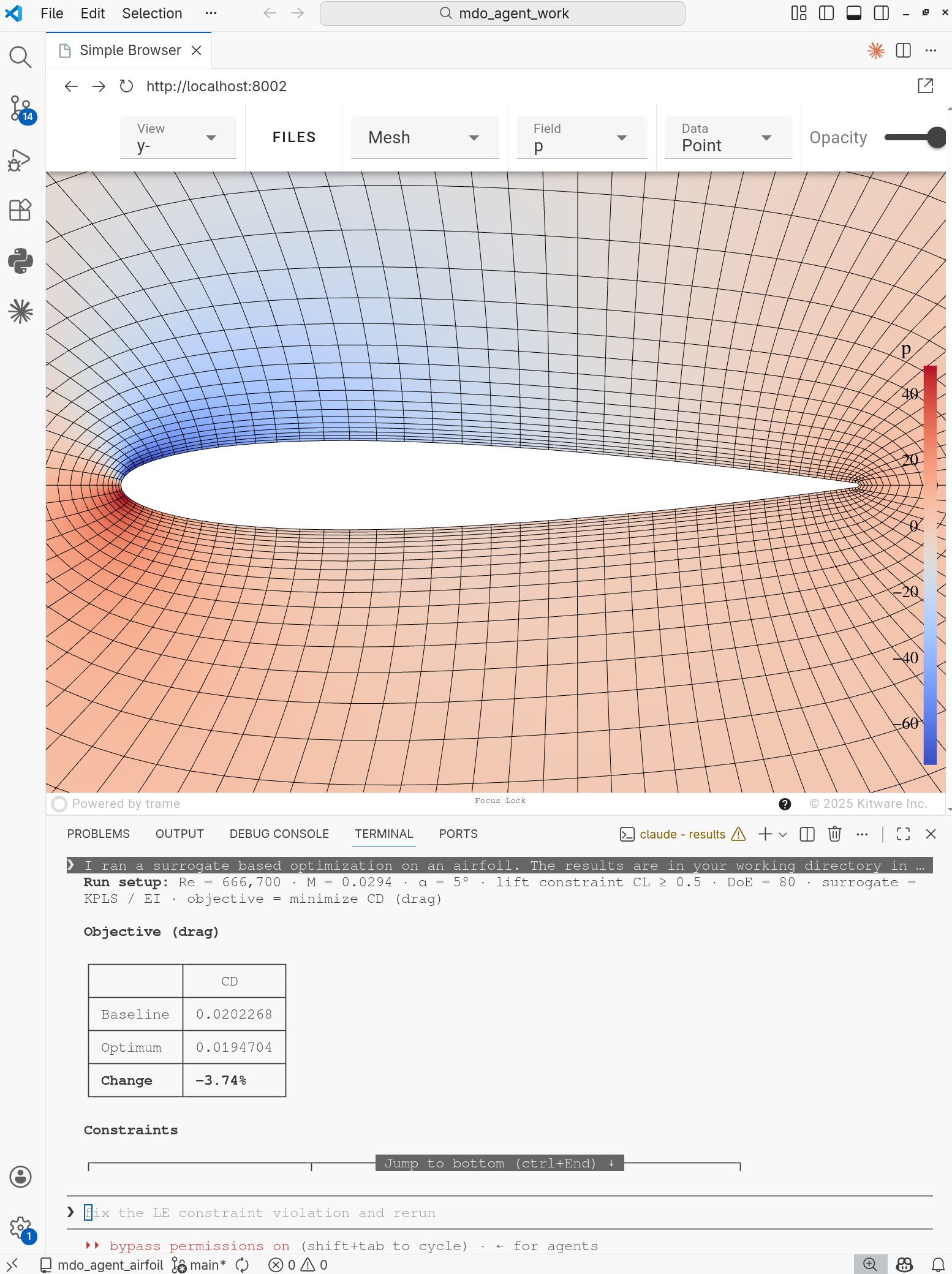
Fig. 6. Surrogate-based aerodynamic shape optimization. Top Left: comparison of the pressure and shape between the baseline and optimized designs. Top Right: Visualizing of the pressure for optimized design in trame. Bot left: Visualizing of the velocity profile for optimized design in trame. Bot right: Visualizing of the pressure for baseline design in trame.
Aerodynamic multipoint optimization
Users can prompt to run a multipoint optimization. The default objective is drag, the design variables are airfoil shape, angle of attack, and weights, the constraints include lift for each scenario, thickness, volume, and leading edge radius. For example,
Generate a multipoint optimization at ma 0.02941, Re 6.67e5, cl [0.5, 0.4], aoa [5 deg, 4 deg], and weights [0.6, 0.4]. Use 4 cores.
The following is the agent-generated figure. Similar to the aerodynamic shape optimization, the drag reduction and constraints can be found in the chat window after the optimization finishes.
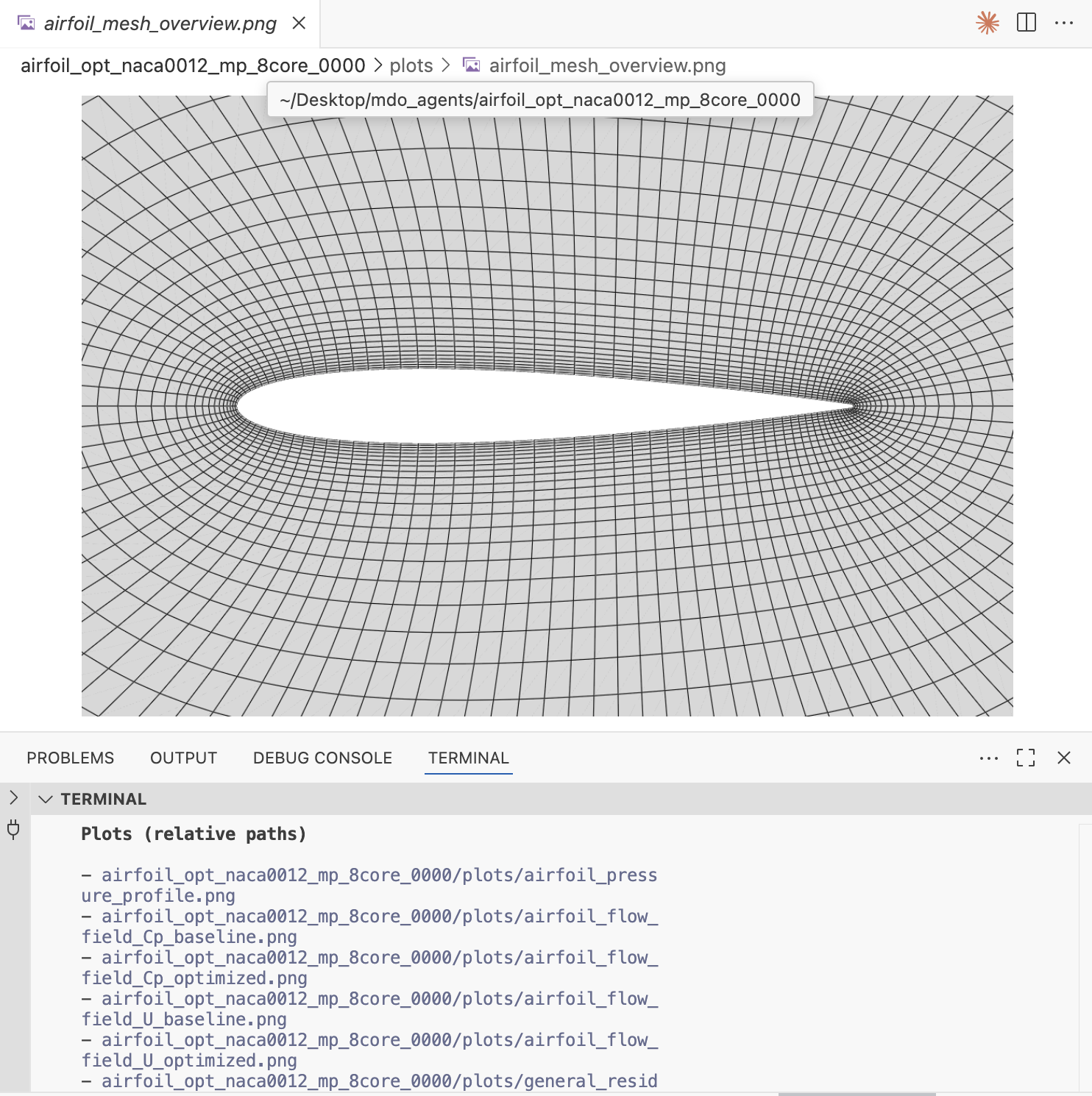
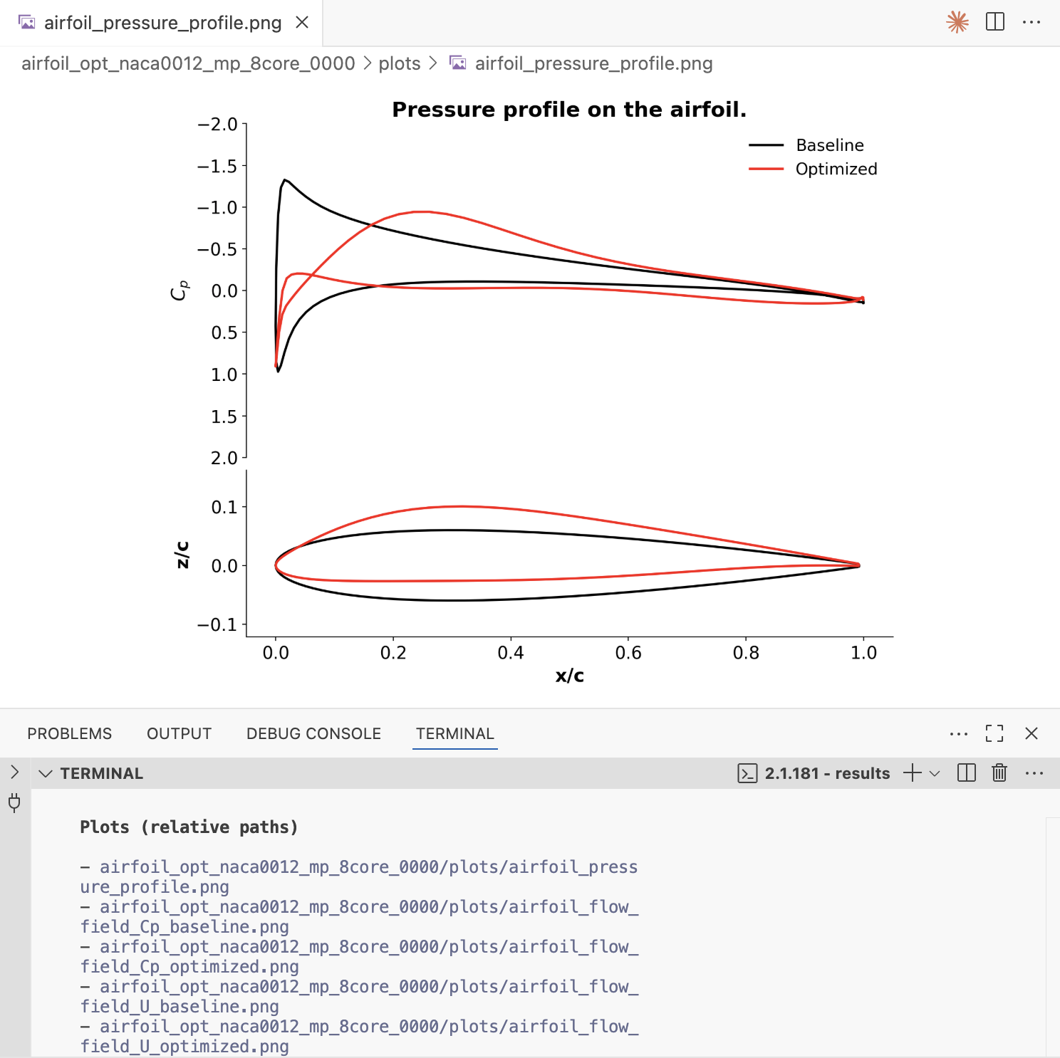
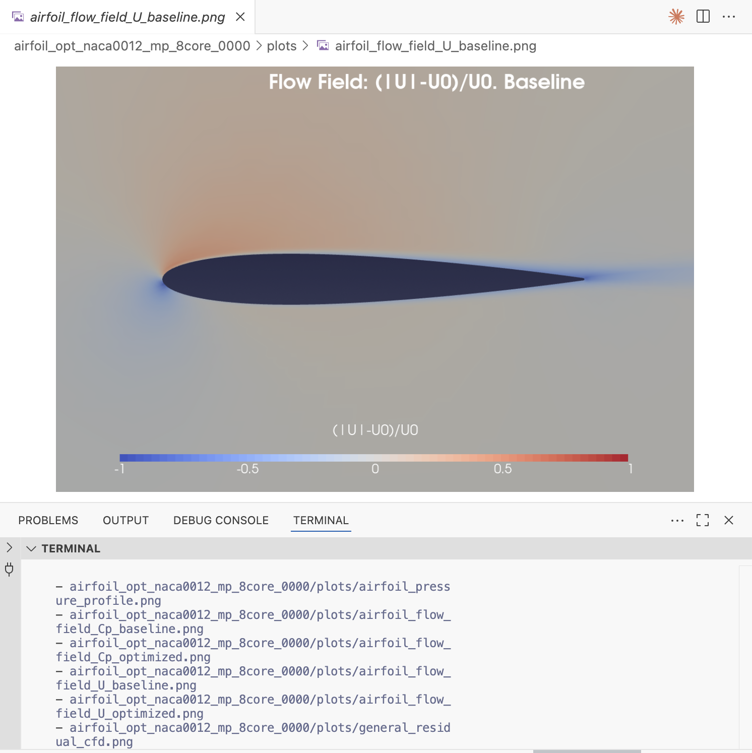
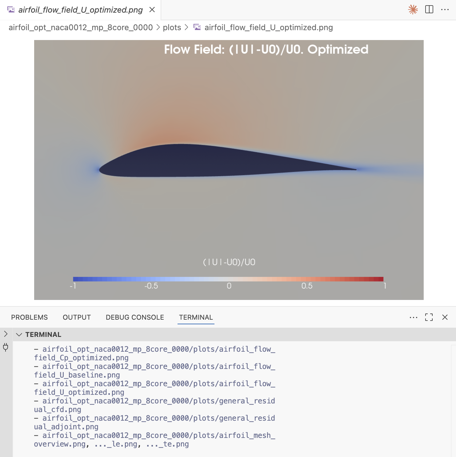
Fig. 7. Aerodynamic multipoint optimization. Top Left: mesh profile generation. Top Right: comparison of the pressure and shape between the baseline and optimzied designs. Bot Left: baseline flow field plot generated in Paraview. Bot Right: optimized flow field plot generated in Paraview.
Generate training samples
Users can prompt to run multiple CFD simulations to generate samples for training machine learning models. For example,
Generate training sample points for NACA0012 airfoil for AOA=1 to 5 degs, and Ma from 0.15 to 0.4. Generate 10 samples..
The following is the agent-generated figure.
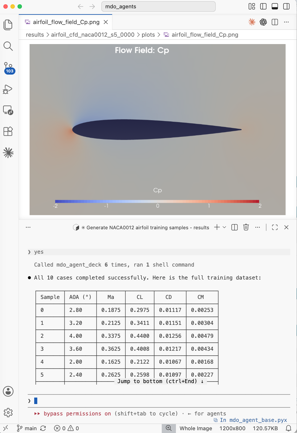
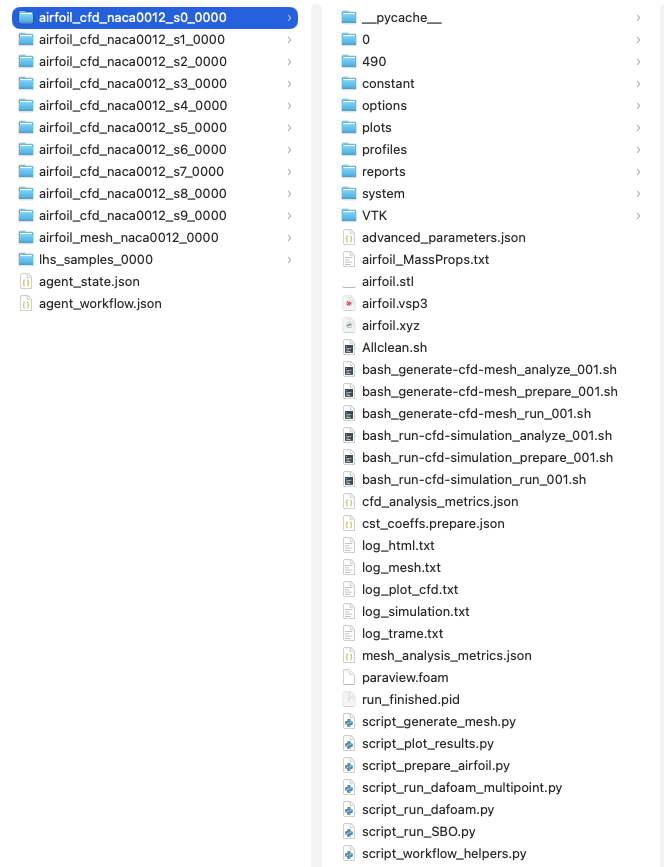
Fig. 8. Left: summary of the CD/CL for all generated samples. Right: Screenshot of the folder structure that contains all the flow fields for each training sample