The following is an aerodynamic shape optimization case for the Onera M6 wing in transonic conditions.
Case: Wing aerodynamic optimization
Geometry: Onera M6 wing
Objective function: Drag coefficient (CD)
Lift coefficient (CL): 0.27
Design variables: 120 FFD points moving in the y direction, five twists, and one angle of attack.
Constraints: volume, thickness, LE/TE, and lift constraints (total number: 114)
Mach number: 0.839 (285 m/s)
Reynolds number: 11.7 million
Mesh cells: ~37,000
Solver: DARhoSimpleCFoam
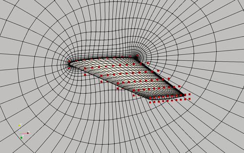
Fig. 1. Mesh and FFD points for the Onera M6 wing.
The “runScript.py” is based on the one used in the NACA0012 transonic case with the following modifications:
-
In “meshOptions”, we set only one symmetry plane, instead of two symmetry planes used in the 2D airfoil case.
-
We compute the number of spanwise FFD points and set it to “nTwist” by calling nTwists = DVGeo.addRefAxis(“bodyAxis”, xFraction=0.25, alignIndex=”k”).
-
We define a function to change the twist at these spanwise FFD sections. Note that we do NOT change the root twist (we already had angle of attack as design variable), so the first element in the twist design variable is the twist at the 2nd spanwise location.
def twist(val, geo): for i in range(1, nTwists): geo.rot_z["bodyAxis"].coef[i] = val[i - 1] -
We call the following functions to add the twist design variable. Again, we have nTwist-1 twists because we do not change the root twist.
DVGeo.addGeoDVGlobal("twist", np.zeros(nTwists - 1), twist, lower=-10.0, upper=10.0, scale=1.0) daOptions["designVar"]["twist"] = {"designVarType": "FFD"} -
The leList and teList are oblique to the y axis. They should be close to the leading and trailing edges but completely within the wing surface.
leList = [[0.01, 0.0, 1e-3], [0.7, 0.0, 1.19]] teList = [[0.79, 0.0, 1e-3], [1.135, 0.0, 1.19]] -
We call the following functions to constrain the leading and trailing edge FFD movements by requiring them to move in the opposite directions. There is no need to manually set up the LE/TE linear constraints, as was done in the 2D airfoil case. Also, there is no need to impose symmetry constraints for k=0 and k=1 since this is a 3D wing case.
# Le/Te constraints
DVCon.addLeTeConstraints(0, "iLow")
DVCon.addLeTeConstraints(0, "iHigh")
To run this case, first download tutorials and untar it. Then go to tutorials-main/Onera_M6_Wing and run the “preProcessing.sh” script to generate the mesh:
./preProcessing.sh
The above script will generate a structured hex mesh using pyHyp. Alternatively, you can generate an unstructured snappy hex mesh by calling:
./preProcessing_snappyHexMesh.sh
Then, use the following command to run the optimization with 8 CPU cores:
mpirun -np 8 python runScript.py 2>&1 | tee logOpt.txt
For the structured hex mesh, the case ran for 50 steps and took about 3 hours using Intel 2.6 GHz CPU with 8 cores on one Skylake node of Stampede 2. According to “logOpt.txt” and “opt_SLSQP.txt”, the initial drag is 0.016597241 and the optimized drag is 0.013540159 with a drag reduction of 18.4%. NOTE: the above numbers are based on a mesh much finer than the default mesh provided in the Onera_M6_wing tutorial.
The evolution of pressure and shape during the optimization is as follows.
Fig. 2. Pressure and shape evolution during the optimization process