The following is a structural optimization case for a plate with a hole in the middle.
Case: Structural optimization for the plate hole configuration
Geometry: Plate hole
Objective function: Weight
Design variables: 24 FFD points moving in the x and y directions
Constraints: Symmetry constraint (total number: 18), max stress constraint
Mesh cells: 4 K
Solver: DASolidDisplacementFoam
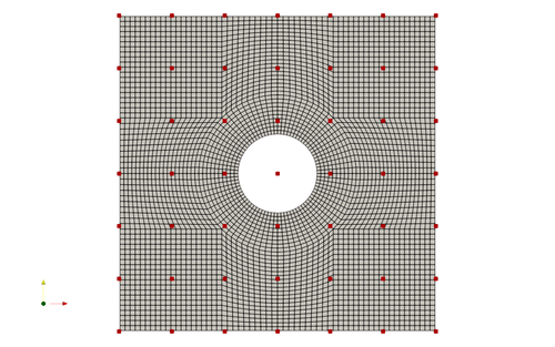
Fig. 1. Mesh and FFD points for the plate hole case
To run this case, first download tutorials and untar it. Then go to tutorials-main/PlateHole_Structure and run the “preProcessing.sh” script to generate the mesh:
./preProcessing.sh
Then, use the following command to run the optimization with 1 CPU cores:
python runScript.py 2>&1 | tee logOpt.txt
After conducting the optimization, use ParaView to ensure the simulation has been completed successfully. There should be 10 geometry iterations which minimize mass while preserving the original maximum stress.
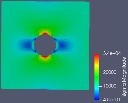
Fig. 2. Stress results and distribution before optimization
Fig. 3. Optimization results and animation
As you can see, the optimization eliminates material to reduce component weight while preserving the maximum stress. The mass is reduced from 11950 to 10701, or a reduction of mass by 10.5 percent. This can be seen in the logOpt.txt output file.
We have gone further to compare the simulation results from OpenFoam to the results from a numerical solution for a plate hole case and the same simulation executed in an established software ANSYS, version 2019 R2. The results are shown below in figure 7 below.
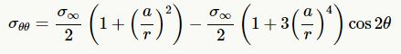
Fig. 4. Stress equation for a plate hole
This equation in Fig 4 assumes the plate has infinite width, which causes some discrepancy near the edge of the plate. The maximum case for this equation occurs at +90 deg and -90 deg.
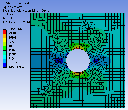
Fig. 5. ANSYS stress results and distribution before optimization with mesh
It was not possible to use the exact constraints as ANSYS would display an error that it was under constrained, so the setup is shown in figure 6. Also, an automated mesh was used which differs from the mesh in OpenFoam. This will result in varying results, but will sufficiently correlate results between OpenFoam and ANSYS solutions.
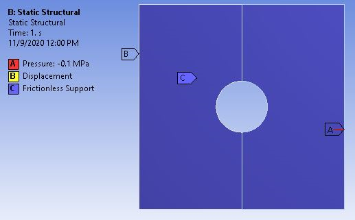
Fig. 6. ANSYS simulation setup
Additionally, by plotting both OpenFoam and ANSYS results against the numerical solution, a comparison can be made between the various methods and tools for stress analysis. The numerical solution is created using the equation shown in Fig 4.
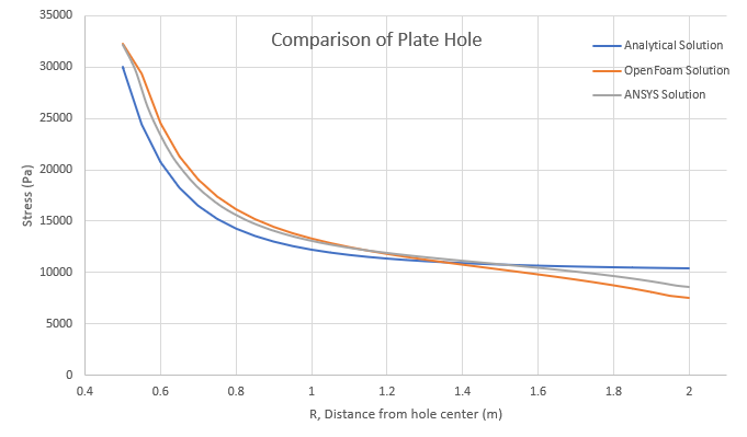
Fig. 7. Plate hole case comparison graph
Both ANSYS and OpenFoam show good relation with the numerical case. OpenFoam shows very good relation to an established tool for finite element structural analysis. Very near the hole, the analysis tools show a higher stress value than the numerical solution. This creates a conservative case for design purposes. On the extremity, the numerical solution has a higher stress than the analysis tools. This is due to the presence of the plate edge. The maximum stress for OpenFoam and ANSYS are 32205 Pa and 32174 Pa, respectively. Compared to the 30000 Pa numerical solution, this creates a percent error of 7.35% for OpenFoam and 7.25% for ANSYS. As for the minimum stress case, OpenFoam and ANSYS result in 7580 Pa and 8580 Pa, respectively. Comparing this again to the numerical solution of 10371 Pa, this creates a percent error of 26.9% for OpenFoam and 17.3% for ANSYS. The hole overestimates stress while the extremity underestimates stress using the simulation tools. Between these two points, the correlation is quite good. The average percent error is 10.7% for OpenFoam and 7.0% for ANSYS.
The validation of OpenFoam’s analysis supports the optimization results. The 10.5% decrease in mass is significant and the plate hole case is common in aerospace with an abundance of fastener holes in many structures.
-By Adam Bodenham