The following is an aerodynamic shape optimization case for the ADODG3 wing configuration.
Case: Wing aerodynamic optimization
Geometry: ADODG3 Wing
Objective function: Drag coefficient (CD)
Lift coefficient (CL): 0.375
Design variables: 120 FFD points, twist, and angle of attack for the shape-only case (total: 126).
Constraints: volume, thickness, LE/TE, and the lift coefficient (total number: 764)
Mach number: 0.3
Reynolds number: 0.22 million
Mesh cells: ~435,000
Solver: DARhoSimpleCFoam
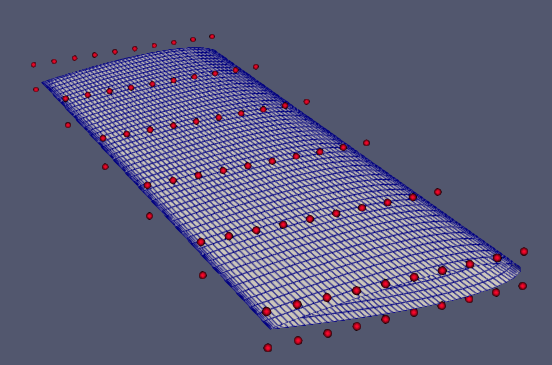
Fig. 1. Mesh and FFD points for the ADODG3 wing.
For the ADODG3 Wing configuration, we create three cases: a shape-only case using “runScript.py”, a planform case using “runScript_planform.py”, and a combined shape and planform case using “runScript_shape_planform.py”.
The shape-only case has the variables aoa, twist, and shape.
The planform case has the variables aoa, taper, and span.
The shape and planform case has all of the previous variables: aoa, twist, shape, taper, and span.
The angle of attack is used consistently for all three cases to facilitate CFD convergence. We select “paralleltoFlow” in “objFunc” to specify the airflow direction, which requires the use of the aoa variable.
The shape-only case has volume, thickness, LE/TE, and lift constraints.
The planform case has only volume and lift constraints. The LE/TE and thickness constraints are redundant in the planform case.
The shape and planform case has volume, thickness, LE/TE, and lift constraints.
The “runScript.py” is similar to the one used in the NACA0012 incompressible case with a few differences:
-
Similarly to the Onera M6 case,, we set FFD points to “nTwist” and do not change the root twist.
def twist(val, geo):
    for i in range(1, nTwists):
        geo.rot_z["bodyAxis"].coef[i] = val[i - 1]
We add the twist variable using the following function.
DVGeo.addGeoDVGlobal("twist", np.zeros(nTwists - 1), twist, lower=-10.0, upper=10.0, scale=1.0) daOptions["designVar"]["twist"] = {"designVarType": "FFD"} - We add the function “checkMeshThreshold” in daOptions to relax the mesh quality criteria.
"checkMeshThreshold": { "maxAspectRatio": 3000.0, "maxNonOrth": 75.0, "maxSkewness": 6.0, "maxIncorrectlyOrientedFaces": 3, } -
In daOptions, we add the function “primalMinResTolDiff” to adjust the convergence tolerance for the primal solver. The value of “primalMinResTolDiff” is multiplied by the value of “primalMinResTol” to loosen the tolerances.
"primalMinResTol": 1.0e-8,
"primalMinResTolDiff": 1.0e4,
The “runScript_planform.py” is the same as the “runScript.py” but with only the aoa, taper, and span design variables.
The “runScript_shape_planform.py” is similar to the “runScript.py” with the following differences:
- We add the function “adjStateOrdering” to ease the convergence of the adjoint equation.
"adjStateOrdering": "cell", -
We change the scaling factor “scaler” for all of the variables except for the angle of attack. This is done to control the relative step sizes of the design variables. We give the variables taper and span significance by scaling them up by a factor of 100 while reducing the impact of the shape variable by scaling it down by a factor of 10.
self.add_design_var("twist", lower=-10.0, upper=10.0, scaler=0.1) self.add_design_var("span", lower=-30.0, upper=30.0, scaler=0.01) self.add_design_var("taper", lower=[0.0, -30.0], upper=30.0, scaler=0.01) self.add_design_var("shape", lower=-1.0, upper=1.0, scaler=10.0) self.add_design_var("aoa", lower=0.0, upper=10.0, scaler=1.0) - As previously stated, the “runscript_shape_planform.py” adds the variables taper and span along with the variables contained in “runScript.py”, twist, aoa, and shape.
To run this case, first, download tutorials and untar it. Then go to tutorials-main/ADODG3_Wing and run the “preProcessing.sh” script to generate the mesh:
./preProcessing.sh
It is recommended to run this tutorial on an HPC. However, the following command can be used to run the optimization with 4 CPU cores:
mpirun -np 4 python runScript.py 2>&1 | tee logOpt.txt
The shape-only case ran for 49 steps and took about 11 hours with 320 cores on 4 Icelake nodes of Stampede 2. According to “opt_SNOPT_summary.txt”, the drag reduction was 8.79%.
 Fig. 2. Pressure and shape evolution during the optimization process for the shape-only case
The planform case ran for 5 steps and took about 1 hour with 320 cores on 4 Icelake nodes of Stampede2. According to “opt_SNOPT_summary.txt”, the drag reduction was 8.47%.
 Fig. 3. Pressure and shape evolution during the optimization process for the subsonic planform case
The shape and planform case ran for 100 steps (exceeding the SNOPT iteration limit) and took about 12 hours with 320 cores on 4 Icelake nodes of Stampede 2. According to “opt_SNOPT_summary.txt”, the drag reduction was 17.2%. It is not recommended to run the case for more than 100 major iterations because of the minimal change in drag after iteration 100.
 Fig. 4. Pressure and shape evolution during the optimization process for the subsonic shape and planform case
To generate the pressure and shape figure of the wing, first reconstruct the processor folders from the optimization into simpler timestamp folders using the following command.
reconstructPar
Next, delete the processor folders.
rm -r processor*
Then, open Paraview and open the “paraview.foam” file. Make sure that the case type selected is “reconstructed”, select “patch/wing” in Mesh Regions, and check the box that says “Camera Parallel Projection. Click “Apply” to view a colored pressure gradient on the ADODG3 Wing. For more details related to post-processing, refer to the post-processing page in Get Started.
The following is a transonic optimization of the same wing as above
Lift coefficient (CL): 0.375
Mach number: 0.7
The shape-only case ran for 103 steps and ran for 72 hours with 72 cores on the Nova HPC. According to “opt_SNOPT_summary.txt”, the drag reduction was 17.4%.
Fig. 5. Pressure and shape evolution during the optimization process for the transonic shape-only case
The shape and planform case ran for 91 steps and ran for 48 hours with 72 cores on the Nova HPC. According to “opt_SNOPT_summary.txt”, the drag reduction was 25.4%.
Fig. 6. Pressure and shape evolution during the optimization process for the transonic shape and planform case
Over the iterations, it is possible to see shock waves as large differentiations in pressure can be seen on the ParaView post-processing images. In the transonic case, the drag reduction is much higher compared to the subsonic cases. This is due to the overall higher drag values that come from the higher Mach numbers, which leaves more room for optimization and drag reduction.