This chapter was written by Ping He.
Learning Objectives:
After reading this chapter, you should be able to:
- Identify the main difference in runScript.py between NACA0012 (2D) and ADODG3 (3D) aerodynamic optimization
- Setup and run a new 3D wing aerodynamic optimization case
Overview of the ADODG3
In the previous chapter, we have learned how to conduct optimization for 2D airfoils. This chapter will extend the optimization to a 3D wing called ADODG3. The following is a summary of the optimization.
Case: 3D Wing aerodynamic optimization
Geometry: ADODG3 Wing
Objective function: Drag coefficient (CD)
Lift coefficient (CL): 0.375
Design variables: 120 FFD points, twist, and angle of attack (total: 126).
Constraints: volume, thickness, LE/TE, and the lift coefficient (total number: 764)
Mach number: 0.3
Reynolds number: 0.22 million
Mesh cells: ~435,000
Solver: DARhoSimpleFoam
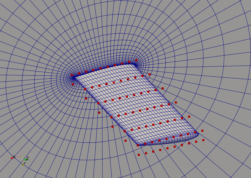
Fig. 1. Mesh and FFD points for the ADODG3 wing.
Differences in preProcessing.sh
We use the pyHyp package to generate 3D mesh. pyHyp requires a structured surface mesh in the .cgns or .xyz (plot3D) format. So in preProcessing.sh, we first download the surface mesh adodg3_surfaceMesh_fine.cgns (this surface mesh was generated in ICEM-CFD).
if [ -f "adodg3_surfaceMesh_fine.cgns.tar.gz" ]; then
  echo "Surface mesh adodg3_surfaceMesh_fine.cgns.tar.gz already exists."
else
  echo "Downloading surface mesh adodg3_surfaceMesh_fine.cgns.tar.gz"
  wget https://github.com/dafoam/files/releases/download/v1.0.0/adodg3_surfaceMesh_fine.cgns.tar.gz
fi

tar -xvf adodg3_surfaceMesh_fine.cgns.tar.gz
Then, we use the cgns_utils to coarsen the surface mesh (reduce the number of surface mesh cells by a factor of 4)
cgns_utils coarsen surfaceMesh_fine.cgns surfaceMesh.cgns
Next, we follow similar steps as in the NACA0012 2D airfoil case to extrude the volume mesh (its parameters are defined in genWingMesh.py) using pyHyp, output the mesh in the plot3D format, and convert the mesh into OpenFOAM format. The rest of the preProcessing.sh code is not shown.
Alternative: Unstructured mesh generation using preProcessing_snappyHexMesh.sh
Alternatively, we can use an unstructured mesh generated by OpenFOAM’s built-in meshing tool snappyHexMesh. We can first download the stl file for the ADODG3 wing geometry
if [ -f "adodg3_triSurface.tar.gz" ]; then
  echo "Geometry already exists."
else
  echo "Downloading geometry adodg3_triSurface.tar.gz"
  wget https://github.com/dafoam/files/releases/download/v1.0.0/adodg3_triSurface.tar.gz
fi
tar -xvf adodg3_triSurface.tar.gz
mv triSurface constant/triSurface
Then, we can run the rest of the commands to use snappyHexMesh to generate the meshes. To make this chapter concise, we skip the snappyHexMesh part. Refer to the Appendix for more details on mesh generations.
Differences in runScript.py
The “runScript.py” is based on the one used in the NACA0012-Subsonic case with the following modifications:
In “meshOptions”, we set only one symmetry plane at z=0, instead of two symmetry planes used in the 2D airfoil case. Note: the purpose of setting the symmetry plane in runScript.py is to make sure the mesh deformation does not change the mesh in the direction that is normal to the symmetry plane. The symmetry plane defined in runScript.py->meshOptions does not need to be the same one defined in OpenFOAM’s constant/polyMesh/boundary file. For example, if you don’t want to deform the mesh at the inlet patch, you can set it as the symmetry plane in runScript.py->meshOptions.
We add a reference axis for the twist variable, and get the number of spanwise FFD point sections as nRefAxPts. In other words, if we have 10 FFD points in the spanwise direction, we will have 10 twist variables. Here we need to give a name to this axis "wingAxis", and this name will be used later when we define the twist function. xFraction=0.25 means the axis is placed at the 25% chordwise (x) direction in the FFD box. alignIndex="k" means the axis rotate with respect to the k index (z axis) in the FFD box. Here we assume the FFD’s i, j, and k indices aligns with the x, y, and z directions.
nRefAxPts = self.geometry.nom_addRefAxis(name="wingAxis", xFraction=0.25, alignIndex="k")
We define a twist function to change the twist at these spanwise FFD sections. Here val, and geo are the two inputs. val is an array that has all the twist values the optimizer want to use, and we need to set these values to the geo object. geo is a pyGeo class, and geo.rot_z["wingAxis"] means the rotation (twist) angle for the wingAxis defined above. Here coef[i] is the ith spanwise twist angle. Note that we do NOT change the root twist (we already had angle of attack as design variable), so the first element in val is the twist at the 2nd spanwise location. That is why we assign val[i-1] to coef[i]. Also note that we use a minus sign for val because we want to use nose-up as positive twist, while pyGeo uses the right-hand rule to determine the rotation direction (which is nose down).
def twist(val, geo):
    for i in range(1, nRefAxPts):
        geo.rot_z["wingAxis"].coef[i] = -val[i - 1]
We call the following functions to add the twist design variable to the geometry component. Again, we have nRefAxPts-1 twists because we do not change the root twist.
self.geometry.nom_addGlobalDV(dvName="twist", value=np.array([0] * (nRefAxPts - 1)), func=twist)
The leList and teList are similar to the NACA0012 case. They should be close to the leading and trailing edges but completely within the wing surface. We use them to define the volume and thickness constraints. Note that we need more than 3 point in the spanwise direction nSpan=25 because the case is 3D. The rule of thumb is that we should use a only a slightly larger number of sample points (in this case is 25 by 30 in the span and chord wise directions) as the FFD points. Here we also add leading and trailing edge constraints, e.g., nom_add_LETEConstraint to fix the leading and trailing edges. volID is the volume index for the FFD block. In this case we have only one block, so volID=0. faceID="iLow" means we make link displacements for the first layer of FFDs in the ith (x) direction. The top and bottom FFD move in the opposite directions for i=0, such that the leading edge does not move. Similarly, faceID="iHigh" means the last layer of FFDs in the ith direction.
leList = [[0.02, 0.0, 1e-3], [0.02, 0.0, 2.9]]
teList = [[0.95, 0.0, 1e-3], [0.95, 0.0, 2.9]]
self.geometry.nom_addThicknessConstraints2D("thickcon", leList, teList, nSpan=25, nChord=30)
self.geometry.nom_addVolumeConstraint("volcon", leList, teList, nSpan=25, nChord=30)
self.geometry.nom_add_LETEConstraint("lecon", volID=0, faceID="iLow")
self.geometry.nom_add_LETEConstraint("tecon", volID=0, faceID="iHigh")
The rest of the runScript.py is similar to the one used in the NACA0012-Subsonic
Questions
TBD