pvOptUMesh is the second graphical user interface (GUI) plugin in the pvOptGUI suite. pvOptUMesh streamlines the process of generating structured meshes from tri-surface mesh (.STL) files using SnappyHexMesh, which can then be used for optimization. This GUI is currently in the beta version.
Load the case and plugin
First, install and open ParaView following the instructions mentioned on this page.
Next, open the pvOptUMesh source, located by opening the sources tab of the toolbar then hovering over pvOptGUI.
Then open a paraview.foam dummy file in the file select option of this source. A zipped tutorial folder containing an example of this dummy file can be downloaded here.
Then click the green apply button on the left, below the ParaView pipeline window. You can also set up the ‘auto-apply’ feature by navigating to edit in the upper toolbar, then selecting settings. Auto-apply is the second setting under the general tab.
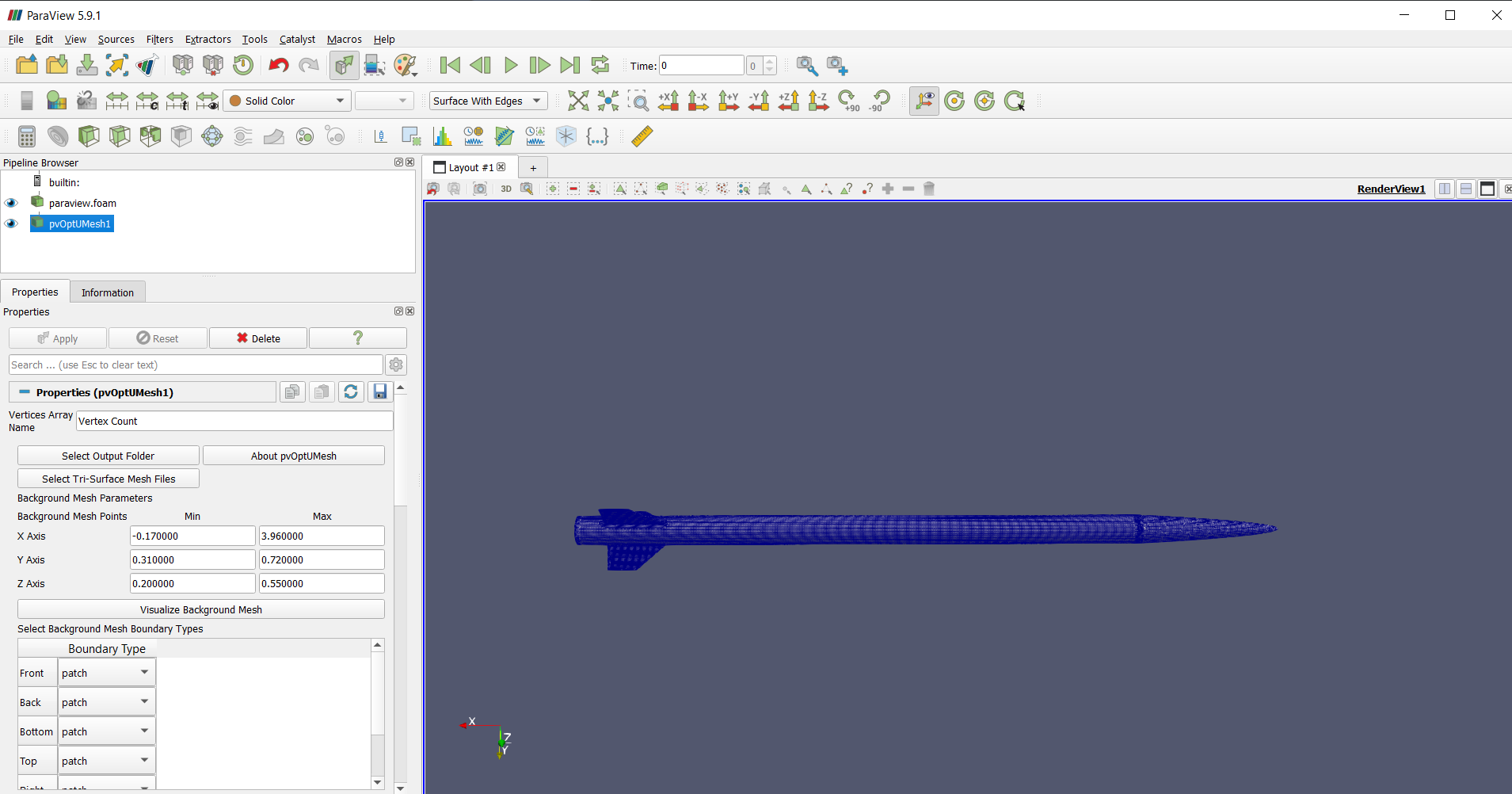
You should now see the pvOptUMesh interface in the panel on the left, below the pipeline, as shown in the following figure.
A message box should appear indicating whether a working Docker version was successfully found on your system, click OK.
Generate the mesh
NOTE: This step requires Docker. If Docker is not found when loading the plugin, the generation files will be created without actually generating the mesh.
First, confirm the output folder is selected. Then click the Select Tri-Surface Mesh Files button to select the .STL files. A file dialog should now appear, select all .STL files that you would like to generate the mesh for. The stl files should be in meters.
After importing the stl files, the bounds for the background mesh block should be filled in with the minimum values to contain your tri-surface mesh files. These values can be increased, but you may get a warning if you try and decrease the size from minimum.
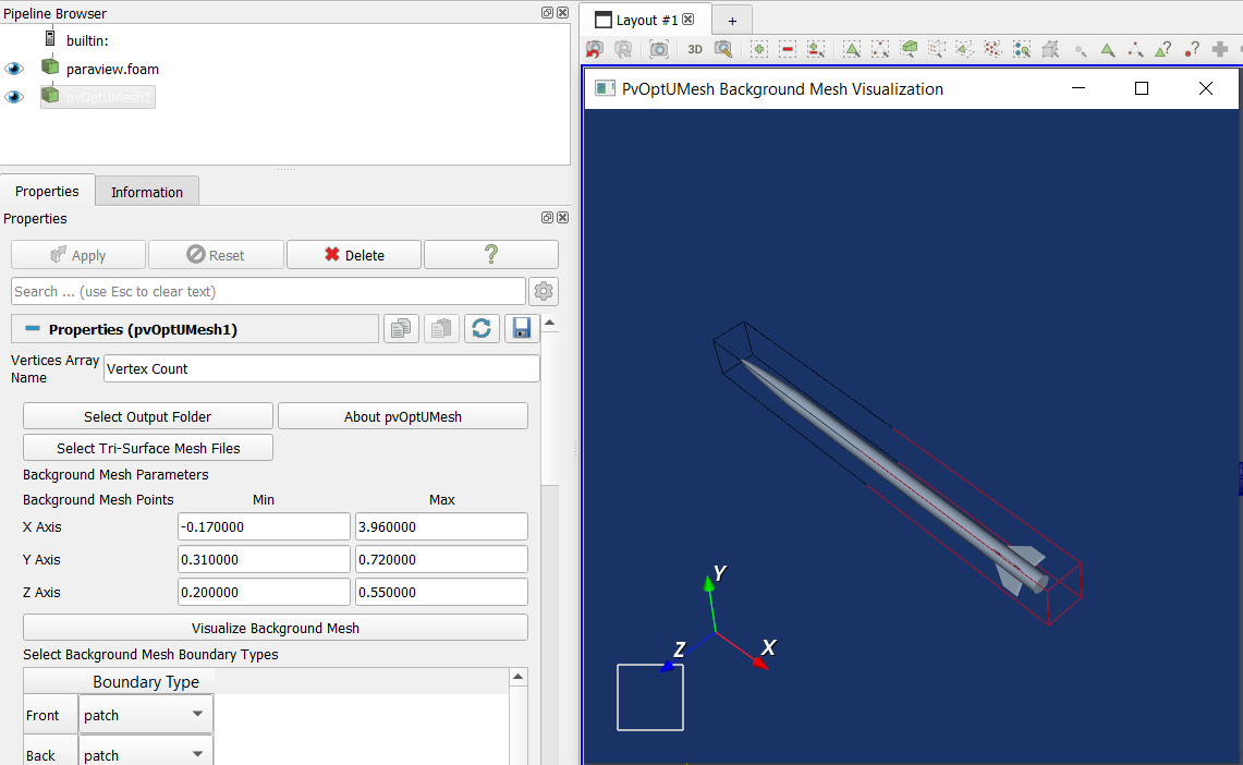
After setting the background mesh bounds, the bounding box can be visualized around the .STL assembly by clicking Visualize Background Mesh.
Now, prescribe the boundary type for each face of the background mesh block
- The options are patch, wall, and symmetry plane
Input the total number of cells in the background mesh
- If the input value does not allow for an aspect ratio of 1, the value will be modified
- If no nearby values are acceptable you may be asked to change the bounds of the background mesh
Input the line level
- Must be an integer
- If advanced setting are enabled, the line level can be set for each .STL file individually
Surface Level
- If advanced settings are enabled, the surface level can be set for each .STL file individually
Prism Level
- Must be an integer
A few other parameters can be adjusted by enabling advanced settings:
The Mesh Location
- Default is to generate an external mesh, but an internal mesh can also be generated
Cells Between Levels
- Number of cells generated between each prism level
- Default is 3
Final Layer Thickness
- Thickness of the final mesh layer at the tri-surface mesh boundary
- Default is 0.5
Max Non-Orthogonality Angle
- Default is 60 degrees
Max Skewness
- Default is 4
Finally, select the Generate Mesh button to start mesh generation. After completion, a message box should appear indicating success or failure.
NOTE: To load a generated mesh to the viewing area in ParaView, navigate to your paraview.foam file in the pipeline, and click refresh and apply in the menu below (you may need to scroll)